

- Home
- About
- Products
- Contact Temperature Sensors
- Cables & Wires
- Mineral Insulated Cables
- Nickel & Thermocouple Alloy
- Industrial Heaters
- Heating Cables and Mats
- Non Contact Temperature Sensors
- Industrial and R&D Furnaces
- Temperature Calibrators
-
Circulating Chiller
- Services
-
Special Products
- Thermal Profiling System
- Industries
- Resources
- Contact Us
- Shop
Search
FAQs
-
Contact and Non-contact method of measurement
Contact method:
This method is used when the body (whose temperature is to be measured) and the sensor(which ismeasuring the temperature) can remain in contact with each other, in other words, we can say that if thebody and the sensor can remain in contact with each other during the measurement of temperature thancontact method is used.
Non-contact method:
This method is used when the body (whose temperature is to be measured) and the sensor (which is measuring the temperature) are not allowed to remain in contact with each other, in other words, we can say that if the body and the sensor are not allowed to remain in contact with each other during the measurement of temperature then non-contact method is used.
-
What is Thermocouple and how it works?
Thermocouple is a pair of dissimilar metal wires joined at one end, which generate a net thermoelectric voltage between open pair according to the temperature difference between the ends.
Working:
- Thermocouple works on Seebeck Effect, which forms the basis of modern thermocouple technology.
- When two different or unlike metals are joined together at two junctions, an electromotive force (emf) is generated at the two junctions. The amount of emf generated is different for different combinations of the metals.
- The junction that is put into the process in which temperature is being measured is called the HOT JUNCTION. The other junction which is at the last point of thermocouple material and which is almost always at some kind of measuring instrument is called the COLD JUNCTION.
-
How to select right thermocouple for your application?
- To select an ideal thermocouple, first we need to understand the need of measurement application.
- Factors affecting temperature change
- Accuracy required- impact of sensor accuracy on overall measurement accuracy.
- Length of deployment
- Thermocouple material selection
- Selection of the Measuring Junction
- Durability
- Range of temperature which is to be measured.
- Determine the maximum and minimum range in which you want to measure the temperature and select the thermocouple with higher Maximum temperature range.
- Check whether the linearity of thermocouple meets the range requirement.
- Environmental Consideration
- Select the correct sheath material to resist chemical reaction.
- Perfect isolation to resist noise protection.
- Thermocouple should withstand vibration and abrasion.
- Appropriate connectors and cables to be used between thermocouple and measuring instruments.
- Appropriate measuring instrument should be used to give an accurate result.
- To select an ideal thermocouple, first we need to understand the need of measurement application.
-
What are the Advantages of Thermocouples and RTD over Thermistors?
- Because Thermistors are semiconductors, they are more susceptible to permanent de-calibration at high temperatures than are RTD's or thermocouple.
- The use of thermistors is generally limited to a few hundred degree Celsius and manufacturers warn that extended exposures will cause the thermistor to drift out of its specified tolerance.
- Thermistors can be made very small which means they will respond quickly to temperature changes. It also means that their small thermal mass makes them especially susceptible to self-heating errors.
- Thermistors are good deal more fragile than RTD's or thermocouple and they must be carefully mounted to avoid crushing or bond separation.
-
What are different Methods of formation of Hot junction?
To form the hot junction, a suitable method has to be adopted to obtain a good electrical contact between the thermocouple wires.
For Chromal/Alumal and other combinations, for use in high temperature measurements, welding is the only method to obtain a suitable joint. For this purpose Tig welding & Laser beam welding is mostly used.Tig welding
Gas tungsten arc welding (GTAW), also known as tungsten inert gas (TIG) welding, is an arc welding process that uses a non-consumable tungsten electrode to produce the weld. The weld area is protected from atmospheric contamination by a shielding gas.
Laser beam welding
Laser beam welding (LBW) is a welding technique used to join multiple pieces of metal through the use of a laser. The beam provides a concentrated heat source, allowing for narrow, deep welds and high welding rates. LBW is a versatile process, capable of welding carbon steels, HSLA steels, stainless steel, aluminum and titanium. The speed of welding is proportional to the amount of power supplied but also depends on the type and thickness of the workpieces.
-
What are the different Thermocouple Standards?
- ASTM E 235: Standard Specification for Thermocouples, Sheathed, Type K and Type N for Nuclear or for other High-Reliability Applications.
- ASTM E 839: Standard Test Methods for Sheathed Thermocouples and Sheathed Thermocouple Cable.
- ASTM E 220: Test Methods for Calibration of Thermocouples by Comparison Techniques
- ASTM E 230: Specification and Temperature-EMF Tables for Standardized Thermocouples.
- ASTM E 585: Standard specification for compacted MI, MS, base metal thermocouple cables.
- ASTM E 608: Standard specification for compacted MI, MS, base metal thermocouples.
- ASTM E 696: Standard specifications for tungsten - rhenium alloy thermocouple wire.
- ASTM E 1652: ASTM E 1652: Standard specification for Magnesium Oxide & Aluminum Oxide powder & crushable insulators used in metal sheathed PRT’s, noble metal thermocouples, base metal thermocouples, and their respective cables.
- IS 12579: Specification for Base Metal Mineral Insulated Thermocouple Cables and Thermocouples.
- GB/T 1598- 2010: Chinese standard for platinum thermocouples.
- IEC 584: International standard for thermocouples.
-
How many Types of Thermocouples available?
Many combinations of materials have been used to produce acceptable thermocouples, each with its own particular application spectrum. However, very few specific types are now easily available, and covering by far the majority of the temperature and environmental applications.
The standard covers the eight specified and most commonly used thermocouples. These thermocouple types can be subdivided in 3 groups, base metal, Noble (rare) metal and Refractory metal thermocouple.Base Metal Thermocouples
Base metal thermocouple types are composed of common, inexpensive metals such as nickel, iron and copper. The thermocouple types E, J, K, N and T are among this group and are the most commonly used type of thermocouple.
Noble Metal Thermocouples
Noble metal thermocouples are manufactured with wire that is made with precious or “noble” metals like Platinum and Rhodium. The main types are R, S and B.
Refractory Metal Thermocouples
Refractory metal thermocouples are manufactured with the exotic metals tungsten and Rhenium. These metals are expensive, difficult to manufacture and wire made with these metals are very brittle.
Thermocouple Type Material + & - Temperature Range (ºC) Application E Chromel & Constantan (Ni-Cr & Cu-Ni) -200 to 900º C Inert media, Oxidizing media J Iron & Constantan (Fe & Cu-Ni) 0 to 750ºC Inert media, Oxidizing media, Reducing media Vacuum K Chromel & Alumel (Ni-Cr & Ni-AI) -200 to 1250ºC Inert media, Oxidizing media N Nicrosil & Nisil (Ni-Cr & Ni-Si) -270 to 1300ºC Inert media, Oxidizing media T Copper & Constantan (Cu & Cu-Ni) -200 to 350ºC Inert media, Oxidizing media, Reducing media Vacuum R 87% Platinum/13% Rhodium &
Platinum
(Pt-Rh & Pt)0 to 1450ºC Inert media, Oxidizing media. S 90% Platinum/10% Rhodium &
Platinum
(Pt-Rh & Pt)0 to 1450ºC Inert media, Oxidizing media, B 70% Platinum/ 30% Rhodium & 94%
Platinum/6% Rhodium
(Pt-Rh & Pt-Rh)0 to 1700ºC Inert media, Oxidizing media. C 95% Tungsten/ 5% Rhenium & 74% Tungsten/ 26% Rhenium 0 to 2320ºC Vacuum inert and reducing G Tungsten & 74% Tungsten/ 26% Rhenium 0 to 2320ºC Vacuum inert and reducing D 97% Tungsten 3% Rhenium & 75% Tungsten/ 25% Rhenium 0 to 2320ºC Vacuum inert and reducing -
What are Noble Metal Thermocouples?
Noble metal thermocouples are manufactured with wire that is made with precious or “noble” metals like Platinum and Rhodium. Noble metal thermocouples can used in oxidizing or inert applications and must be used with a ceramic protection tube surrounding the thermocouple element. These sensors are usually fragile and must not be used in applications that are reducing or in applications that contain metallic vapors.
- Type R - Type R thermocouples are made with a platinum/13% rhodium positive leg and a pure platinum negative leg. The temperature range for type R is 0 to 1450ºC (32 - 2642 ºF).
- Type S - Type S thermocouples are made with a platinum/10% rhodium positive leg and a pure platinum negative leg. The temperature range for type S is 0 to 1450ºC (32 - 2642 ºF).
- Type B - Type B thermocouples are made with a platinum/30% rhodium positive leg and a platinum/6% Rhodium negative leg. The temperature range for type B is 0 to 1700ºC (32 - 3092ºF).
-
What are Refractory Metal Thermocouples?
Refractory metal thermocouples are manufactured with wire that is made from the exotic metals Tungsten and Rhenium. These metals are expensive, difficult to manufacture and wire made with these metals are very brittle. These thermocouples are intended to be used in vacuum furnaces at extremely high temperatures and must never be used in the presence of oxygen at temperatures above 300°C. There are several different combinations of alloys that have been used in the past but only one (C Type) generally used at this time.
- Type C - Type C - The type C thermocouple is made with a tungsten/5% rhenium positive leg and tungsten 26% Rhenium negative leg and has a temperature range of 0 - 2320°C (32 - 4208 °F).
- Type G- Type G thermocouple technically also known as WM26Re. The type G thermocouple has alloy combination of tungsten (W) as positive lead and tungsten + 26% Rhenium (W-26% Re) as negative lead. Maximum useful temperature range of this thermocouple is 0 to 2320°C.
- Type D- Type D- Type D thermocouple technically also known as W3ReM25Re. Type D thermocouple has alloy combination of tungsten + 3% rhenium (W-3%Re) as positive lead and tungsten + 25 % Rhenium (W-56% Re) as negative lead. Maximum useful temperature range of this thermocouple is 0 to 2320°C./li>
-
Applications of Thermocouples
Thermocouples are suitable for measuring over a large temperature range, up to 2300ºC. They are less suitable for applications where smaller temperature differences need to be measured with high accuracy, for example the range 0-100ºC with 0.1 ºC accuracy. For such applications thermistors and resistance temperature detectors are more suitable. Applications include temperature measurement for kilns, gas turbine exhaust, diesel engines, and other industrial processes. Some other applications are as follows:
- Steel Industry
- Cement Industry
- Pharmaceutical Industry
- Petrochemical Industry
- Nuclear Industry
- Power Industry
- Laboratories
- Furnace Industry
-
Types of Thermocouple Constructions
There are two types of thermocouple construction used most commonly. These are MI (Mineral Insulated) Thermocouples & Non-MI Thermocouples.
Mineral Insulated Thermocouples:
Mineral (Mostly Magnesium Oxide) insulated thermocouples, are used in many process and laboratory applications. They are rugged in nature and bendable, and their fairly high temperature ratings make MgO thermocouples a popular choice for a multitude of temperature measuring applications.
MgO sensors are constructed by placing an element or elements into a sheath of a suitable material and size, insulating the elements from themselves and the sheath with loose filled or crushable Magnesium Oxide powder or insulators, and then swaging or drawing the filled sheath down to its final reduced size. The swaging process produces an element with highly compacted MgO insulation and provides high dielectric strength insulation between the elements themselves and their sheath.
Mineral insulated Thermocouples consist of thermocouple wire embedded in a densely packed refractory oxide powder insulate all enclosed in a seamless, drawn metal sheath (usually stainless steel).
At one end cores and sheath are welded from a “hot” junction. At the other end, the thermocouple is connected to a “transition” of extension wires, connecting head or connector.
Non M.I. Thermocouples
In Non-M.I. thermocouples, thermocouple wires are either insulated with ceramic beads or ceramic tubes, after insulation of ceramic, covered by a metal sheath (usually stainless steel) and some form of termination (extension lead, connecting head or connector for example) is provided. In this type of construction thermocouple wires are protected from the measuring environment when a sheath protection is provided. The sheath material is dependent on the measuring environment usually stainless steel is used. According to the corrosive environment sheath selection is changed.
This construction does not provide flexibility & not found in small sizes. Not too good mechanical strength.
In Non M.I. construction sheath may be of ceramic or metal as per suitability.
Exposed, Grounded and Ungrounded all types of junctions are formed in both the M.I, & Non M.I. construction.
-
Advantages of Mineral Insulated Thermocouples
- Small over all dimension and high flexibility, which enable temperature measurement in location with poor accessibility.
- Good mechanical strength.
- Protection of the thermo element wires against oxidation, corrosion and contamination.
- Fast thermal response.
The mineral oxides used for insulation are highly hygroscopic and open-ended cables must be effectively sealed (usually with epoxy resins) to prevent moisture take-up. A carefully prepared mineral insulated thermocouple will normally have a high value of Insulation Resistance (many hundreds of Mega Ohms).
-
Measuring Junction
Three alternative tip configurations are usually offered:
- An exposed (measuring) junction is recommended for themeasurement of flowing or static non-corrosive gas temperature whenthe greatest sensitivity and quickest response is required.
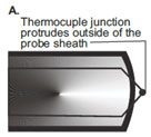
- An insulated junction is more suitable for corrosive media althoughthe thermal response is slower. In some applications where more thanone thermocouple connects to the associated instrumentation,insulation may be essential to avoid spurious signals occurring in themeasuring circuits. If not specified, this is the standard.
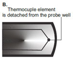
- An earthed (grounded) junction is also suitable for corrosive mediaand for high pressure applications. It provides faster response thanthe insulated junction and protection not offered by the exposedjunction.
- An exposed (measuring) junction is recommended for themeasurement of flowing or static non-corrosive gas temperature whenthe greatest sensitivity and quickest response is required.
-
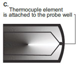
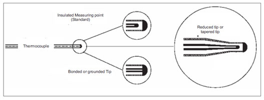
Mineral Insulated thermocouple Tip Style
The junction tip of Mineral insulated thermocouple can be of three types as described previously. The tip can be insulated, grounded and reduced type.
- Insulated Tip: Insulated hot end junctions are suitable for most applications, especially where low EMF pick-up is essential. High insulation resistance is enhanced due to extreme compaction of the high purity MgO powder insulation.
- Grounded Tip: Bonded or grounded junctions offer a slightly faster temperature response than the insulated junction type. Not recommended for multi-point instrumentation.
- Reduced Tip: These junctions are ideal for applications where low mass and extremely fast response times are required, together with good mechanical strength. Reduced tip can be provided on 1.0 to 6.0 mm diameter thermocouples.
-
Characteristics of thermocouple
Tolerances on Temperature Reading
Tolerance denotes the maximum allowable value obtained by subtracting the temperature reading or the temperature at the hot junction from the standard temperature converted from the applicable temperature EMF table.
Maximum Operating Temperature
Operating temperature limit means the upper temperature where thermocouple can be used continuously. Maximum limit means the upper temperature where thermocouple can be used temporarily for short period of time owing to unavoidable circumstances.
Principal factors that affect the life of a thermocouple are:
- Temperature: Thermocouple life decreases by about 50% when an increase of 500 °C occurs.
- Diameter: By doubling the diameter of the wire, the life increases by 2-3 times.
- Thermic cycling: When thermocouples are exposed to thermic cycling from room temperature to above 500ºC, their life decreases by about 50% compared to a thermocouple used continuously at the same temperature.
- Protection: When thermocouples are covered by a protective sheath and placed into ceramic insulators, their life is considerably extended.
Thermocouple Response Times
The response time for a thermocouple is usually defined as the time taken for the thermal voltage (output) to reach 63.2% of maximum for the step change temperature. It is dependent on several parameters including the thermocouple dimension, construction, tip configuration and the nature of the medium in which the sensor is located.
Immersion Length
Thermocouple assemblies are'' tip'' sensing devices which lend them to both surface and immersion applications depending on their construction. However immersion type must be used carefully to avoid error due to stem conduction from the process which can result in a high or low reading respectively. A general rule is to immerse into the medium to a minimum of 4 times the outside diameter of the sheath; no quantitative data applies but care must be exercised in order to obtain meaningful results.
Surface Temperature Measurement
Although thermocouple assemblies are primarily tip sensing devices, the use of protection tubes renders surface sensing impractical. Physically, the probe does not lend itself to surface presentation and stem conduction would cause reading errors. If thermocouple is to be used reliably for surface sensing, it must be either exposed, welded junction from with very small thermal mass or be housed in a construction, which permits true surface contact when attaching to the surface.
-
Applications of thermocouples in Steel Industry
Thermocouples are having significant role in Steel industries. Area wise, various types of thermocouples are used in different units of steel industry:
STOVE DOME THERMOCOUPLE
Stove dome/hot blast stove is one of the most critical sections in the steel industry. The hot blast has 3 stage operations, either on gas, on blast or bottled up (ready and waiting to be put on blast).
Temperature is one of the major parameter for controlling this critical process. The temperature inside the blast furnace is about 1100°C and high pressure. The high temperature and high pressure makes the assembly very critical.
COKE OVEN THERMOCOUPLE
Coke is the most important raw material fed into the blast furnace in terms of its effect on blast furnace operation and hot metal quality. The coke making process involves carbonization of coal to high temperatures (1100°C) in an oxygen deficient atmosphere in order to concentrate the carbon.
HEARTH REFRACTORY THERMOCOUPLE
Refractory thermocouples are very important for the startup phase and running phase of the refractory in the steel plants. These are normally very long length thermocouples (up to 40 meters) in mineral insulated construction. Thermocouples of various lengths can be grouped together in a single flange, for a particular area of the furnace.
DRI KILN THERMOCOUPLES
Fast response thermocouple normally K type with miniature or Standard connector for DRI kiln application and normally used with a hand held indicator for checking immediate temperature.
-
Applications of thermocouples in Cement Industry
Thermocouple are widely used in different units of Cement plant:
- Kiln
- Clinker Temp.
- Pre-Heater.
- ESP (Electro-Static Precipitators) system.
- Coal Silo.
-
Applications of thermocouples in Pharmaceutical Industry
In pharmaceutical industries, thermocouples are used for Validation and Process. Various areas of applications are:
FOR VALIDATION
- Autoclave
- Bung Processor
- Dry Heat Sterilizer (tunnel)
- Lypholizer (FD)
FOR PROCESS
- Tank
- Vessels
- Boiler
- Reactor
- Distillation Column
- Dryer
- Granulation
-
Applications of thermocouples in Petrochemical Industry
- Thermocouple are used in for different applications in Petrochemical Industry :
- Multi point thermocouples for Reactors, Crackers and Liquefied gas tanks.
- MI thermocouples for Tube Surface
- Sulphur Recovery Unit
- Cracker and Liquefied Gas in Tanks
- Fluid Catalytic Cracking Unit(FCCU)
-
RTD and its working
Resistance thermometer use metals that alter their electric resistance when heated. Platinum is most commonly used material for industrial RTD. However copper and Nickel are also used for some applications. The resistance at 0ºC is called R and it is important parameter to be defined. The most commonly used RTD element is of Platinum with resistance of 100O at 0ºC. RTD has a positive temperature coefficient. Normally industrial RTD are used up to temperature range of 400ºC.
Working:
- In RTD, The change in resistance value is very small with respect to the temperature. So, the bridged circuit is used.
- Constant electric current is supplied to bridged circuit and voltage drop is measured across the resistor, through which resistance is measured. Thereby, the temperature can also be determined.
- This temperature is determined by converting the RTD resistance value using a calibration expression.
-
How to select right RTD for your application?
- Select the right one among various RTDs on the basis of temperature range and accuracy requirement.
- RTDs work best under the temperature range of -200ºC-850ºC.
- If you need a higher level of accuracy then RTD is better option.
- RTD's are commonly used in applications where repeatability and accuracy are important considerations. Properly constructed Platinum RTD's have very repeatable resistance vs. temperature characteristics over time.
- RTD can be used where Stability, Sensitivity and Linearity is important parameter.
- RTD Design selection:
- Good heat transition between sheath and the temperature probe to permit short response time and high measuring accuracy.
- RTD designshould withstand the process vibrations.
- Select the right one among various RTDs on the basis of temperature range and accuracy requirement.
-
Applications of RTD
Resistance thermometers offer the greatest benefits relative to other thermometer types in these situations:
- Accuracy and stability are the foremost goals of the Application.
- Accuracy must extend over a wide temperature range
- Area, rather than point, sensing improves control
- A high degree of standardization is desirable
The major application areas of RTDs are:
- Food Processing Industry
- Plastic Industry
- Pharmaceutical industry
- Air, gas and liquid temperature measurement
- Textile industry
- Exhaust gas measurement
- Industrial electronics
- Military & Aerospace
-
Equation of RTD
At 0° C, A Platinum RTD has a resistance of 100 Ω & a temperature co-efficient of about 0.00385 Ω / Ω / °C. These non-linearties are described in Callender-Van Duesen equation. This equation consists of both a linear portion & a non- linear portion.
Range 200 to 0ºC: R (t) [Ω] = R (1 + At + Bt2 + C (t - 100ºC) t3)
Range 0 to 850ºC: R? (t) [O] = R (1 + At + Bt?)
With: R0 is resistance at 0 ºC
A = 3, 9083 x 10ˉ³ °Cˉ¹
B = -5,775 x 10ˉ⁷ °Cˉ²
C = -4,183 x 10ˉ¹² °Cˉ⁴ -
RTD Materials
The criterion for selecting a material to make an RTD is:
- The material must be malleable so that it can be formed into small wires
- It must have a repeatable and stable slope or curve.
- The material should also be resistant to corrosion.
- The material should be low cost.
- It is preferred that the material have a linear resistance verses temperature slope.
Some of the common RTD materials are platinum, copper, nickel, Balco (an alloy of 70% nickel and 30 % iron). These metals have the advantage that they can be manufactured to a very high degree of purity and are, consequently, available with highly reproducible temperature/resistance characteristics. These metals can also be drawn to a fine diameter wires required in resistance thermometry.
-
Characteristics of various materials used as RTD
Element Material Temperature Range (ºC) Resistance
Ratio (R100/R0)Resistivity
x10-8 (O.m)Relative Cost Linearity Deviation (0-100ºC) Platinum -200 to 850 1.3925 to 1.385 11 1100 +0.12 Copper -200 to 260 1.427 1.72 1 0 Nickel -80 to 300 1.672 7.8 20 -1.61 Balco -200 to 230 1.518 20 15 -1.17 As shown in table, although copper is cheapest, it also has the lowest resistivity and therefore requires inconveniently large sensing elements. On the other hand, even as nickel and nickel alloy have high resistivity, their resistance versus temperature coefficients are non-linear. They are also sensitive to strain and their resistivity suffer from an inflexion around the Curie point (358ºC) that makes the deviation of their resistance/ temperature expressions more complicated.
This platinum which not only has a high resistivity (more than six times that of copper) but also a high degree of stability and a wide temperature range. Although platinum is expensive it can be drawn into fine wires or strips and we only require small amounts for manufacturing RTDs. As a noble metal, it has minimum susceptibility to contamination.
The presence of impurities is undesirable since diffusion, segregation and evaporation may occur in service, resulting in a lack of stability. The resistivity is also sensitive to internal strains. Thus, it is essential that the platinum should remain in a fully annealed condition i.e. it should be annealed at a temperature higher than the maximum temperature of service.
-
Temperature Rating for RTD'S.
The maximum temperature rating for RTD's is based on two different factors. First is the element material.Platinum RTD's can be used as high as 650°C (1202F). Other materials are much lower in temperature rating and vary from material to material. The other determining factor for temperature rating is probe construction. There are construction considerations used in each of these different styles making them ideal for use in each of those ranges. Noone style is good for all ranges.
-
Types of RTD’s
Platinum RTDs typically are provided in two classes:Class A and Class B.
Class A is considered high accuracy and has an ice point tolerance of 0.06 ohms.
Class B is standard accuracy and has an ice point tolerance of 0.12 ohms. Class B is widely used by most industries.The accuracy will decrease with temperature. Class A will have an accuracy of 0.43 ohms ( 1.45°C) at 600°C and class B will be 1.06 ohms ( 3.3°C) at 600°C.Other accuracy classes like 1/3, 1/5, 1/10 DIN of class B are available.
Platinum resistance temperature sensors (PRT) They offer excellent accuracy over a wide temperature range (from -200 to +850°C).
Other resistance value options
RTD elements are also available with resistances of 200, 500, and 1000 Ω at 0°C. Such type of RTDs is normally known as PT200, PT500, and PT1000 respectively. These RTDs have the same temperature coefficients as previously described, but because of their higher resistances at 0°C, they provide more resistance change per degree, allowing for greater resolution.Standard Platinum RTDs (SPRTs)
-
Tolerance table for types of RTD's according to IEC751.
Temperature 1/10 Din (+-ºC) 1/5 Din (+-ºC) 1/3 Din (+-ºC) Class A (+-ºC) Class B (+-ºC) -100ºC 0.080 1.160 0.267 0.350 0.800 -50ºC 0.055 0.110 0.183 0.250 0.550 0ºC 0.030 0.060 0.100 0.150 0.300 50ºC 0.055 0.110 0.183 0.250 0.550 100ºC 0.080 0.160 0.267 0.350 0.800 150ºC 0.105 0.210 0.350 0.450 1.050 200ºC 0.130 0.260 0.433 0.550 1.300 250ºC 0.155 0.310 0.517 0.650 1.550 300ºC 0.180 0.360 0.600 0.750 1.800 350ºC 0.205 0.410 0.683 0.850 2.050 400ºC 0.230 0.460 0.767 0.950 2.300 -
Standard Platinum RTDs
The ITS-90 (International Temperature Scale of 1990- used as a worldwide practical temperature scale in national metrology labs like NIST, NPL) is made up of a number of fixed reference points with various interpolating devices used to define the scale between points. A special set of PRTs, called SPRTs, are used to perform the interpolation in such labs over the ranges 13.8033 K (Triple point of Equilibrium Hydrogen) to the Freezing point of silver, 971.78ºC.

-
RTD Standards
There are two standards for platinum RTDs: The European standard (also known as the DIN or IEC standard) and the American standard.
The European standard, also known as the DIN or IEC standard, is considered the world-wide standard for platinum RTDs. This standard, DIN/IEC 60751 (or simply IEC751), requires the RTD to have an electrical resistance of 100.00 Ω at 0ºC and a temperature coefficient of resistance (TCR) of 0.00385 Ω /Ω/ºC between 0 and 100ºC. There are three resistance tolerances for Thin Film.RTDs specified in IEC60751:
Class AA (Formerly 1/3B) = ± (0.1+0.0017×t) °C or 100.00 ± 0.04Ω at 0°C
Class A = ± (0.15+0.002×t) °C or 100.00 ± 0.06Ω at 0°C
Class B = ± (0.3+0.005×t) °C or 100.00 ± 0.12Ω at 0°CAlso, one special class not included in DIN/IEC60751:
Class 1/10B = ±1/10 (0.3+0.005×t) °C or 100.00 ± 0.012Ω at 0°C -
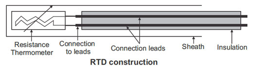
Construction of RTD
The RTD elements nearly always require insulated leads attached. At temperatures below about 250 ºC PVC, silicon rubber or PTFE insulators are used. Above this, glass fiber or ceramic are used. The measuring point, and usually most of the leads, requires a housing or protective sleeve, often made of a metal alloy which is chemically inert to the process being monitored. Selecting and designing protection sheaths can require more care than the actual sensor, as the sheath must withstand chemical or physical attack and provide convenient attachment points.
-
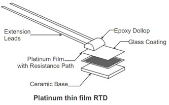
Platinum thin film RTD
TThe European standard, also known as the DIN or IEC standard, is considered the world-wide standard for platinum RTDs. This standard, DIN/IEC 60751 (or simply IEC751), requires the RTD to have an electrical resistance of 100.00 Ω at 0ºC and a temperature coefficient of resistance (TCR) of 0.00385 Ω /Ω/ºC between 0 and 100ºC. There are three resistance tolerances for Thin Film.
-
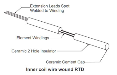
Inner coil wound RTD
This type of element is normally manufactured using platinum wire. Very small platinum wire (0.02 mm) is coiled and then slid into a small 2 holes ceramic insulator. Larger extension leads are then spot welded to the ends of the platinum wire and cemented in place. Some manufacturers backfill the bores of the insulator with ceramic powder, once the coil have been inserted. This keeps the coils away from moving and shorting against each other. The end opposite the extension leads is capped with ceramic cement also.
-
Outer wound RTD element
The outer wound RTD element is made by winding the sensing element wire around a center mandrill, which is usually made of ceramic. This winding is then coated with glass or some other insulating material to protect and secure the windings. The winding wires are then spot welded to extension leads and secured to the body with ceramic cement or epoxy.
Each of the types has their advantages. The thin film is the least expensive to manufacture and also the most rugged. They can also be manufactured in very small sizes. The inner coil wire wound style is the most accurate. It is however, more expensive to manufacture and does not perform well in high vibration applications. The outer wound element is similar in cost to the inner coil element. It is not as accurate as the inner coil style but is more rugged.

-
Lead wire Configurations for RTD
RTDs are available with three different lead wire configurations. The selection of lead wire configuration is based on desired accuracy and instrumentation to be used for the measurement.
-
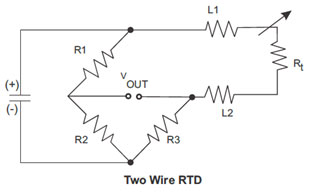
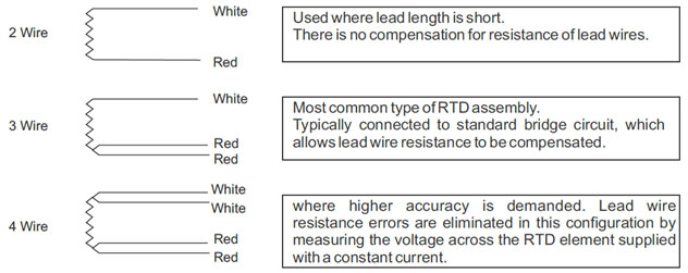
Two wire RTD
The two wires RTD is the simplest wire configuration. One wire is attached to each side of the element. A measure can be taken by any device equipped to measure resistance, including basic Volt Ohm Meters (VOM).
This is the least accurate way of measuring temperature, due to the fact that the lead wire resistance is in series with the sensing element. The lead wire is at a different temperature than the sensing element and also has different resistance verses temperature characteristics. The longer the lead wire greater will be the effect on the measurement.
-
Three Wire RTD
The three wires RTD is the most popular configuration for use in industrial applications. In order to minimize the effects of the lead resistances, a three-wire configuration can be used. Using this method the two leads to the sensor are on adjoining arms. There is a lead resistance in each arm of the bridge so that the resistance is cancelled out, so long as the two lead resistances are accurately the same. This configuration allows up to 600 meters of cable.
When used correctly, the three wire configuration eliminates the series resistance. This permits an accurate measurement of the sensing element. Two of the leads are connected to one side of the sensing element and the single lead to the other side. The resistance in L1 and L3 should be matched as close as possible; this will cause the lead resistance to cancel them. The color code for a three wire RTD is two red wires and one white.

-
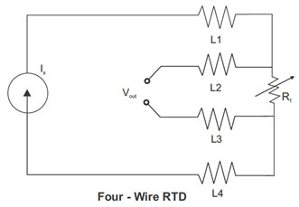
Four wire RTD
A four wire RTD is the most accurate method to measure an RTD. It is primarily used in laboratories and is seldom seen in an industrial application. The four-wire resistance thermometer configuration increases the accuracy and reliability of the resistance being measured: the resistance error due to lead wire resistance is zero.
A four wire RTD circuit removes the effect of mismatched resistances on the lead wires. A constant current is passed through L1 and L4, L2 and L3 measure the voltage drop across the RTD element. The color code for a four wire RTD is usually two red wires and two white wires. The following diagram illustrates a typical four wire measurement.
-
Lead configuration and color code
- It comprises of a thin-walled and flexible mineral insulated sheath cable made up of stainless steel.
- The cable contains low resistance inner wires made of copper embedded in pressed fireproof magnesium oxide.
- The temperature sensor is connected to the inner wires and fitted in a protective tube.
- Protective tube and sheathed cable are welded together hermetically.
- Good heat transfer between protective tube and temperature sensor allows fast response time and high measuring accuracies.
- The flexible probe tube allows temperature measurement at locations that are not easily accessible.
- They are used in difficult measurement application with strong vibrations as well as at all measuring positions where flexibility and ease of replacement are needed.
- Areas of application are to be found in chemical plants, power stations, motors, as well as in machine construction and building installation and in general industrial applications.
-
Mineral Insulated RTD
Mineral-Insulated resistance thermometers (M.I.) are equipped in general with Platinum-measuring resistors Pt100 Ω to DIN IEC 751. The inner (Cu) conductors are embedded in a closely compacted, inert mineral powder (MgO); the measuring resistor will be connected to the inner conductors, is also embedded and is surrounded by the metal sheath to form a hermetically sealed assembly. Sometimes inner conductor of constantan and nickel are also used.
The sheath functions as a useful protective cover in many situations. They are applied in locations where fast response, reduced space and or vibration resistance is a need. They can be furnished with a fixed cable or with a special plug which allows rapid fitting or exchange.
Mineral-insulated RTD temperature probes consist of a flexible, thin-walled stainless steel mineral insulated cable, in which low ohmic conductor copper wires are embedded in pressed, heat resistant magnesium oxide.The temperature probe is connected to the wires of the internal conductors and accommodated in a stainless steel sheath. Thermowell and mineral-insulated cable are welded to one another.
The good heat transition between the sheath and the temperature probe permits short response times and high measuring accuracy. The vibration resistant (shake proof) design guarantees a long operating life. Temperature measurements at measuring points difficult to access, are possible, thanks to the flexible mineral-insulated cable. The smallest bending radius is 5 times the outer diameter.
-
Potential source of errors with RTD
Resistance thermometer systems are susceptible to three types of errors: The inherent tolerances built into the thermometers, gradients between the thermometer and the medium to be sensed, and errors introduced along the path between the sensor and readout or control instrument. Some sources of error are electrical; others result from the mechanical construction of the thermometer.
-
Role of Interchangeability/Conformity for RTD.
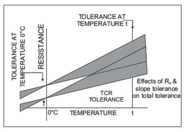
Conformity specifies the amount of resistance a thermometer is allowed to deviate from a standard curve (such as the curve produced by the Callendar-Van Dusen equation).
A tolerance at the reference temperature is usually 0ºC, and a tolerance on the slope or TCR. Below shown figure states that a resistance thermometer conforms most closely to its curve at the reference temperature, while the resistance fans out above and below this reference.
Interchangeability between two thermometers is no more than twice the value of their Conformity. Commercial platinum resistance thermometer elements are available with extremely tight tolerances, to within 0.026ºC in some cases. When interchangeability is an overriding consideration, the specified may consider other means to achieve it. For example, manufacturers may alter their calibration procedures to fix the reference temperature and tightest tolerance at a point other than 0ºC.
-
Role of Sensitivity for RTD
The resistance change per degree change in temperature is a function of base resistance and TCR (Temperature Coefficient of Resistance).
Although a thermometer with higher sensitivity is not necessarily more accurate, a larger signal simplifies output electronics and is less susceptible to lead wire effects and electrical noise. In addition, a larger resistance produces the same voltage output with less measuring current, which helps to limit self-heating of the thermometer element.
-
Role of Insulation Resistance for RTD
If the sensing element and leads are not completely insulated from the case, a shunting effect occurs in which the case becomes a parallel resistor and lowers apparent readings. In most industrial thermometers, with specified insulation Resistances in the 100-MΩ ranges, error approaches zero. The manufacturer must take care to seal water-absorbing materials. The shunting effect decreases with low-resistance elements, which accounts for the use of 25.5 PRT's in laboratory measurements.
-
Role of Self Heating for RTD
A resistance thermometer is a passive resistance sensor; it requires a measuring current to produce a useful signal. Because this measuring current heats the element wire above the true ambient temperature, errors will result unless the extra heat is dissipated. Self-heating is most often expressed in mW/ºC, which is the power in milliwatts (1000 I²R) required to raise the thermometers internal temperature by 1ºC. The higher the mW/ºC figure, the lower the Self Heating.
As an example, assume a 5 mA measuring current is driven through 100 platinum RTD at 100ºC.
Self-heating is specified as 50 mW/ºC in water moving at 3 ft/sec. The amount of heat generated is:
1000 mW x (0.005 A)2 x (138.5) = 3.5 mW
The self-heating error is:
(3.5 mW) / (50 mW/ºC) = 0.07ºCThe generated heat increases with higher sensor element resistance (when a constant current measurement device is used), or with increasing measuring current.
The resulting error is inversely proportional to the ability of the thermometer to shed extra heat; which in turn depends on thermometer materials, construction, and environment.
The worst self-heating occurs when a high resistance is packed into a small body. Thin film elements, with little surface area to dissipate heat, are an example. Self-heating also depends on the medium in which the thermometer is immersed. Error in still air may be over 100 times greater than in moving water.
-
Role Time Constant plays for RTD
A time constant indicates the responsiveness of a resistance thermometer to temperature change. A common expression is the time it takes a thermometer to reflect 63.2% of a step temperature change in moving water. Response speed depends on the mass of the thermometer and the rate at which heat transfers from the outer surface to the sensing element. A rapid time constant reduces errors in a system subject to rapid temperature changes.
-
Role Repeatability plays for RTD
The degree of accord between two successive readings with a thermometer is its repeatability. Loss of repeatability results from permanent or temporary changes to the resistance characteristics of the element and may be caused by exposing the thermometer to temperatures at or beyond the endpoints of its specified range. A repeatability test cycles the thermometer between low and high temperatures; any change to R is noted. A typical repeatability rating for 0ºC industrial platinum resistance thermometers is 0.1ºC.
-
Role Stability plays for RTD
Stability is long-term drift in thermometer readings. A typical specification would limit drift to 0.1ºC per year for rated operation. Normal services at points well within the temperature rating typically cause much less drift. Drift is a consequence of the element material, with platinum being the most stable; encapsulating materials, which could contaminate the element; and mechanical stress placed on the element by expansion of winding bobbins or other supporting structures.
-
Role of packaging and thermal transfer in construction of RTD
Sheaths and other structures surrounding resistive elements should maximize heat transfer from the sensed medium, minimize heat transfer from ambient which can alter readings, and provide necessary protection of the elements.
Proper materials and construction can dramatically improve reading accuracy. One strategy practicable only with wire-wound resistance thermometers versus thermistors, thermocouples, and solid-state devices are temperature averaging. An element may be wound to average temperature over lengths of up to 100feet.
-
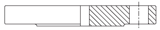
Industrial RTD Probes
The encased probe is the standard resistance thermometer configuration for industrial process control and machinery protection. Most probe cases are stainless steel or Inconel to withstand high temperatures, although other materials offer advantages at intermediate ranges.
For example, the tip-sensitive probe of below Figure copper-alloy tip which conducts heat 20 times better than stainless steel. This design improves thermal contact with sensed surfaces and reduces errors from conduction along the sheath.
 >
>Standard probe diameters range from 0.125 - 0.250”. Smaller probes respond faster when directly immersed, but larger probes may fit more snugly in standard Thermowells. Probe lengths range from a few inches to ten feet or more.
-
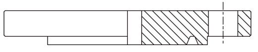
Probe Assemblies
Selection depends on the nature of the medium being sensed and cost requirements. Direct immersion of a probe into a liquid requires a fitting with a pipe thread, which may be adjustable or welded on the probe.
Figure shows a typical assembly, with one thread for mounting the probe and another for a connection head. Connection heads provide a transition between probe leads and external signal wires.
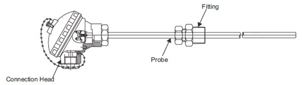
Mounting in a solid material is best accomplished with a spring-loaded holder, which may be fixed or adjustable. Spring loading provides good contact of the probe tip against the bottom of the hole and dampens potentially damaging vibration. When liquids are particularly corrosive, under high pressure, or fast-flowing, a thermowell may be necessary. A thermowell is a tube, closed at one end, which protects the probe and allows its removal without breaking the liquid seal.
-
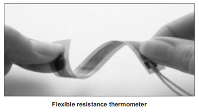
Flexible Resistance Thermometers
Unlike thermocouple junctions, which can be welded directly to metal surfaces, resistance thermometers present a certain amount of bulk; and heat losses to ambient air may affect readings. Small flat elements, such as thin films, may mount on surfaces, but fragile element and lead wire connections make installation difficult.
Figure shows a flexible resistance thermometer with a wire-wound sensing element sandwiched between insulating layers. It conforms closely to sensed surfaces, and has thin insulation to readily transmit heat to the sensing element. The wire element may be wound to nearly any size to average out temperature gradients, and the flexible construction can withstand extreme shock and vibration.
-
Special Purpose Resistance Thermometers
Resistance thermometers readily adapt to most process control and thermal equipment designs. The user may specify cases with axial leads for circuit board mounting, flat packages for clamping to surfaces, miniature cases for embedment into metal blocks, and any sheaths and fittings which can be produced by a machine shop. In addition, wire windings may be configured to sense over large areas.
-
Where to use RTDs?
In summary, resistance thermometers offer the greatest benefits relative to other thermometer types in these situations:
- Accuracy and stability are the foremost goals of the Application.
- Accuracy must extend over a wide temperature range
- Area, rather than point, sensing improves control
- A high degree of standardization is desirable
-
Advantages of RTDs
Advantages of resistance thermometers are:
- High accuracy
- Low drift
- Wide operating range
- Suitable for precision applications
-
Limitations of RTDs
- RTDs in Industrial applications are rarely used above 660 ºC. At temperatures above 660 ºC it becomes increasingly difficult to prevent the platinum from becoming contaminated by impurities from the metal sheath of the thermometer. This is why laboratory standard thermometers replace the metal sheath with a glass construction.
- At very low temperatures, say below -270 ºC (or 3 K), due to the fact that there are very few photons, the resistance of an RTD is mainly determined by impurities and boundary scattering and thus basically independent of temperature. As a result, the sensitivity of the RTD is essentially zero and therefore not useful.
- Compared to thermistors, platinum RTDs are less sensitive to small temperature changes and have a slower response time. However, thermistors have a smaller temperature range and stability
-
Thermowell and its working
Thermowell provide protection for temperature probes against unfavorable operating conditions such as corrosive media, physical impact (e.g. clinker in furnaces) and high pressure gas or liquid. Their use also permits quick and easy probe interchanging without the need to open-up the process.
It is closed-end reentrant tube designed for insertion of a temperature-sensing element, and provided with means for a pressure-tight attachment to a vessel.
Thermowells are typically constructed of solid drilled-out bar stock and are designed to protect a temperature sensors from flow, high pressure and harsh environment.
Working:
- Thermowells are hidden in pipes and are rarely seen. Thermowells are permanently placed into pipes, tanks or sumps so that temperature measurement probes can be inserted into the pipe to measure the contents temperature.
- Welding and brazing is important for the installation requiring seal. The pipe thread provides mechanical strength, and the weld or braze provides the seal.
- Installing temperature sensor assembles into thermowell or directly into the process requires the use of some kind of brass or stainless steel fitting. Fitting include various threaded unions, bayonet cap (and adapters) and flange.
- Adjustable compression fitting are used directly on probe to achieve the required insertion length in the process and to ensure the proper sheathing of probes into thermowell.
-
How to select right Thermowell for your application?
- Select the thermowell material according to the temperature range and the environment (corrosive, oxidizing etc.) in which it is to be used.
- These wells can be made from different materials like SS304, SS316, HRS446, Inconel, Monel, Ceramic, etc.
- According to the construction of Thermowell (Steeped Shank, Straight Shank, Tapered Shank)
- Steeped Shank- Provide faster response time and lower drag force.
- Straight Shank- Extremely strong, but response time is slower and drag force on the fluid flow is high.
- Tapered Shank- Provide good response time and strength.
- Thermowell Insertion Length
- For best temperature measurement accuracy, the “U” dimension should be long enough to permit the entire temperature-sensitive part of the measuring instrument to project into the medium being measured.
Liquid temperature measurement: One inch or greater.
Gas temperature measurement:- three inches or greater.
- For best temperature measurement accuracy, the “U” dimension should be long enough to permit the entire temperature-sensitive part of the measuring instrument to project into the medium being measured.
- Resistance to vibration.
- Fluid flowing past the well forms a turbulent wake (the Von Karman Trail), which has a definite frequency based on the diameter of the well and the velocity of the fluid.
- The thermowell must have sufficient stiffness so that the wake frequency will never equal the natural frequency of the thermowell itself. If the natural frequency of the well were to coincide with the wake frequency, the well would vibrate to destruction and break off.
- To avoid the Thermowell failures caused by excessive pressure, drag forces, high temperature, corrosion, vibrations, it is recommended to run thermowell calculations based on your applications:
- Maximum or operating temperature
- Maximum or operating pressure
- Fluid(gas or liquid) velocity
- Fluid Density.
- Select the thermowell material according to the temperature range and the environment (corrosive, oxidizing etc.) in which it is to be used.
-
Applications of Thermowells
Thermowells provide protection for temperature probes against unfavorable operating conditions such as corrosive media, physical impact (e.g. clinker in furnaces) and high pressure gas or liquid. Their use also permits quick and easy probe interchanging without the need to “open-up” the process. The main application areas are:
- Protection tube are used in thermocouples
- Insures integrity in high pressure applications
- Smaller wells are used in low pressure applications
- Straight wells are used in corrosive and erosive environment
- For applications where a quick response to changes in temperature is required, fabricated pockets may be fitted with a reduced tip.
One-piece Thermowells are suited to the highest process loads, depending on their design. Thus in the petrochemical industry, one-piece thermocouples are now used almost exclusively.
-
Protection tubes for Thermocouples and RTDs
Sheath material ranges from mild and stainless steel to refractory oxides (Ceramics) and a variety of exotic material including rare metals. Sensor inserts are fabricated unit which is comprised by a sensor and a terminal base; the sensor is housed in a stainless steel insert tube, usually of 6 or 8mm diameter and, then it is inserted into the actual protection tube. Good sheathing with physical contact between the insert tip and sheath end is essential to ensure good heat transfer. Spring contact is used in the terminal base to maintain this contact. This arrangement facilitates easy replacement of the sensor whenever required.
In general, there are two types of protection tubes:
- Metallic protection tubes
- Non-metallic protection tubes
-
Metallic and Non-Metallic Sheathing for Thermocouples and RTDs
Metallic tube, most commonly stainless steel, has mechanical advantage and higher thermal conductivity; they are generally immune to thermal shock. Metallic sheath can be used at temperature up to 1150ºC. Ceramics are superior when high purity is required to avoid sensor or product being contaminated at elevated temperature.
-
Ceramic Sheath for thermocouples and RTDs
Ceramic sheath's main application ranges between 1000 to 1800 ºC. They may be in direct contact with the medium or may be used as a gas-tight inner sheath to separate the thermocouple from the actual metal protection tube. They should be mounted in hanging position above 1200ºC to prevent distortion or fracture due to bending stresses. Even hairline cracks can lead to contamination of the thermocouple resulting in drift or failure. The wall thickness of the material is also important; thin walled tube is preferable to larger wall thickness. Cracks frequently developed if they are given excessively rapid temperature changes when they are quickly removed from hot furnace.
-
Metallic Protection Tube
- Metallic protection tubes are composed of different types of metals like 304 S.S, 321 S.S, Inconel 600, Inconel 825, UMCO, Kanthal A1, Hastelloy B, Monel, Platinum, Titanium, Tantalum, Molybdenum etc.
- Operating Temperature range is from 250ºC to 2200ºC.
- Metallic Protection tubes are excellent heat resistant.
- Can you please let me know best image size as this one is also being cut off in screen shot attached.
-
Non-Metallic Protection Tubes
- Non-metallic tubes are composed of different types of non-metals like Refractory oxide recrystallized Aluminum oxide, Silicon Carbide, Silicon Nitride, Cermet, Quartz, Tungsten Carbide etc.
- Operating range is from 300ºC to 1700ºC
- Good resistance to chemical attack. Mechanical strength is good but thermal shock should be avoided.
- Less corrosive to acids and alkalis.
-
Most common types of Thermowells
According to their connection to process
- Threaded
- Socket Weld
- Flanged Welded
According to their production method
- Fabricated Thermowell
- Bar-stock thermowell
- Van-stone thermowell
-
Fabricates Thermowells
Fabricated Thermowells are manufactured from tubes which are sealed by a solid welded tip at the process. It means that the stem of thermowell is manufactured from tube and tip is made separately, than both these parts are welded by utilizing suitable welding process. The flange is also joined to this assembly by welding process. Fabricated Thermowells are generally recommended for low to medium process loads. Connection to the pipe or vessel may be done by means of thread, flange or weld. Standard threads used in fabricated thermowell are NPT, BSP (Pl), BSP (Tr), API & metric thread. The thread size is dependent on the application. Standard sizes range from 1/8” to 2”. For applications where a quick response to changes in temperature is required, fabricated pockets may be fitted with a reduced tip.
-
Barstock Thermowells
Such thermowell bodies are machined and drilled from solid bar stock. This results in a non-welded water tight unit. In this Immersion tip is also made by same material along with stem. In such type of thermowell, no welding process is required for stem and tip production. Flange can be weld according to requirement. Bar-Stock thermowell is also known as “Solid drilled thermowell”. Single piece Thermowells are manufactured from a complete element or bar stock. One-piece Thermowells are suited to the highest process loads, depending on their design. Thus internationally or in the petrochemical industry, one-piece thermocouples are now used almost exclusively. Connection to the pipe or vessel may be done by means of thread, flange or weld. Standard threads are NPT, BSP (P), BSP (Tr), API & metric tread. The thread size is dependent on the application, but 3/4” and 1” are common.
-
Van stone Thermowells
In van stone thermowell, stem, tip and sub part of flange all these three prepared by using single bar or rod material. There is no need of welding for these three parts of thermowell. The flange sub-part serves as a gasket in such type of thermowell. On this sub-part flange is used according to requirement.
-
Thermowell tip profiles
Tapered
The outside diameter decreases gradually along the immersion length. Used for high velocity applications.
Flat Tip
It one end has flat surface. Used in low pressure applications or where flow characteristics around the thermowell are not important.
Domed Tip
Such thermowell has semi-spherical tip at one end of thermowell. Used in higher pressure applications or where flow characteristics around the thermowell are important. This ensures a high degree of mechanical strength without losing the sensitivity or accuracy of the indicator
Spherical Tip
For spherical tip, special drill is used with a tip angle of 118ºC for production of thermowell. To achieve a possible uniform wall thickness, the tip is ball shaped or spherical in shape. Used in higher pressure applications or where flow characteristics around the thermowell are important. This ensures a high degree of mechanical strength without losing the sensitivity or accuracy of the indicator.
-
Basic construction of Thermowells
Shank Construction
- Q Dimension: The thickest part of the shank of the well on the hot side of the process connection or flange. It is dependent on the bore size and the process connection size.
- Bore Size The inside diameter of thermowell. In other words, the diameter of the internal cylindrical cavity of a thermowell or protection tube Standard bore sizes are 6.5 mm, 8.5 mm.
- Immersion (“U”) Length: The length of a thermowell or protection tube below the mounting threads, flange, bushing, etc. extending into the process area. The “U” length is measured from the bottom of the process connection to the tip of the thermowell.
- Lagging Extension (“T”) Length: The length of a thermowell, in addition to the standard head lengths, required to make the head of the thermowell accessible and this enable the probe to extend through insulation or walls.
- Internal Mounting Thread: The thread within the thermowell for attaching a temperature device of the union and nipple extension for a thermowell assembly.
-
Types of flange faces for Thermowells
Raised Face (RF)
The Raised Face type is the most applied flange type, and is easily to identify. It is referred to as a raised face because the gasket surfaces are raised above the bolting circle face.
Ring-Type Joint (RTJ)
RTJ flanges have grooves cut into their faces which steel ring gaskets. The flanges seal when tightened bolts compress the gasket between the flanges into the grooves, deforming (or Coining) the gasket to make intimate contact inside the grooves, creating a metal to metal seal. Ring Type Joint gaskets are designed to seal by "initial line contact" or wedging action between the mating flange and the gasket. Ring Type Joint gaskets* are metallic sealing rings, suitable for high-pressure and high-temperature applications.
Flat Face (FF) The flat face (full face) flange has a gasket surface in the same plane as the bolting circle face. Applications using flat face flanges are frequently those in which the mating flange or flanged fitting is made from a casting. Flat face flanges are never to be bolted to a raised face flange.

-
Types of welding on Thermowells
Welding is a process of joining two metals by heating the metals to a suitable temperature. It may be done with or without the application of pressure, and with or without filler.
Types:
Full Penetration Welding- This type of welding ensures a fully welded interface between the two parts and is generally the strongest joint.
Partial Penetration Welding- This type consists of a partially welded interface with filler metal being laid on the surface of the two metals.
-
Welding procedure specification (WPS) and procedure qualification record (PQR) for Thermowells
A WPS is a document that describes how welding is to be carried out in production. They are recommended for all welding operations and many application codes and standards make them mandatory.
The purpose of the document is to guide welders to the accepted procedures so that repeatable and trusted welding techniques are used. A WPS is developed for each material alloy and for each welding type used.
A WPS is supported by a Procedure Qualification Record (PQR or WPQR). A PQR is a record of a test weld performed and tested (more rigorously) to ensure that the procedure will produce a good weld.
The variables required to be documented are typically such items as:
- Welding process used, size, type and classification of filler alloy.
- Type and thickness of base material welded.
- Type and polarity of welding current, amps and volts recorded.
- Travel speed during welding, welding position, type and dimensions of joint design.
- Preheating temperature, inter-pass temperature, post weld heat treatment details, and others.
In addition to the recording of all the welding variables used during the test, in order to qualify a welding procedure, details of the inspection and test results must also be recorded. These records must show that the inspection and testing has proven that the weld samples have met or exceeded the specified standard requirement.
-
Thermowell Special Coating
Different types of coating are carried out in Thermowells. Some are as follows: Metal Thermowells with Tungsten Carbide / Ceramic / PTFE / PVDF / PFA Coatings.
Sr. No. Coating Thickness Operating Temperature(ºC) Features 1 Tungsten
Carbide
Coated0.5-1.0mm Below 650ºC Tungsten carbide coating offers effective- wear resistance coating, as it offers exceptionally high hardness level ( maximum 74 HRC hardness). It is resistance to high temperature and corrosion & high abrasive condition. 2 Teflon Coated 0.5-1.0mm 200ºC Teflon coating provides a dry film lubricant whitch provides excellent resistance against corrosion and chemicals. 3 Boron Nitride
Coated0.5mm 900ºC Boron nitride protects surface witch comes in contact with molten metal (specially aluminum). Boron nitride inhabits corrosion and chemical attacks, and provide easier release and longer life. 4 Zirconia Coated 0.5-0.1mm 1800ºC Zirconia coating produces a hard and chemically resistant protective layer suitable for high temperature and corrosion. 5 Alumina
Coating0.5-1.0mm 1200ºC Alumina coating provides a high temperature abrasive protection. 6 Stellite Coating 0.5-1.0mm 1200ºC Stellite coating provides very good abrasion resistance and good chemical corrosion resistance. -
Tests on Thermowells
- Material Test
- Dimensional Test
- Hydrostatic Pressure Test
- Dye Penetrant Inspection
- Radiography
-
Material test for Thermowells
Chemical- By PMI(Positive Material Identification).
Physical- By Tensile, Elongation, Hardness, Micro & Macro examination, IGC tests. -
Dimensional test for Thermowells
The Thermowell must be checked according to specified dimension given in drawing.
-
Hydrostatic test for Thermowells
A hydrostatic pressure test is a way in which leaks can be found in pressure vessels such as pipelines and plumbing. The test involves placing water, which is often dyed for visibility, in the thermowell at the required pressure to ensure that it will not leak or be damaged. It is the most common method employed for testing pipes and vessels. Using this test helps maintain safety standards and durability of a vessel over time. Newly manufactured pieces are initially qualified using the hydrostatic test.
-
Dye penetrant Inspection for Thermowells
Dye penetrant inspection (DPI), also called liquid penetrant inspection (LPI) or penetrant testing (PT), is a widely applied and low-cost inspection method used to locate surface-breaking defects in all non-porous materials (metals, plastics, or ceramics). LPI is used to detect casting, forging and welding surface defects such as hairline cracks, surface porosity, leaks in new products, and fatigue cracks on in-service components.
-
Radiography test for Thermowells
Radiographic Testing (RT), or industrial radiography, is a nondestructive testing (NDT) method of inspecting materials for hidden flaws by using the ability of short wavelength electromagnetic radiation (high energy photons) to penetrate various materials. irregularities and flows that can be detected which includes - cracks, voids, thickness, lack of fusion, lack of penetration, porosity and misalignment.
-
Criteria for selection of Thermowells
Materials the Longevity Factor
The selection of material is the most important factor for thermowell life.The material selected is based on the temperature of the application and the process medium.
Connection-The Installation Factor
All threaded well are made by easily welded or brazed materials.Welding and brazing is important for the installation requiring seal. The pipe thread provides mechanical strength, and the weld or braze provides the seal. Flanged wells(other than van stone type) consist of a bar stocks well which is solidly welded to a top quality flange. Standard construction uses a primary "J" groove weld and a bevel groove clean fillet. This double welded construction eliminates the possibility of crevice corrosion since no open joint are exposed from either inside or outside the installation. Socket weld well are simple to install, simply weld them into place.
Insertion Length-The Accuracy Factor
The distance from the tip of the well to the underside of the thread or other connection is defined as the insertion length (designated as "U"). For best accuracy this length should be greater enough to permit the entire temperature sensitive part of element to project into the medium being measured. A properly installed element: in liquid, the element should be immersed up to its sensitive length plus one inch, and in air or gas, the element should be immersed up to its sensitive length plus three inches.
Bore Size-The Interchangeability Factor
Almost all installation uses several type of temperature measuring sensor. The selection of a standard bore diameter can produce extreme flexibility within the plant. The same well can accommodate thermocouple, resistance thermometer, and bimetal thermometer.
Tapered or Straight Well- the Velocity Rating Factor
Tapered shank provides greater stiffness with same sensitivity. The higher strength to weight ratio give these wells higher natural frequency than the equivalent length straight shank well thus permitting operation at higher fluid velocity.
-
Low fluid velocity for Thermowells
At low velocities, the risk of thermowell failure is minimal and does not usually require frequency calculations. If the following criteria are met, the designer may elect to wave calculation requirements.
- Maximum fluid velocity is less than 2.1 ft/sec. [0.46 M/s].
- Wall thickness at "A" support diameter minus "b" bore diameter ≥ 0.376" [9.55mm].
- “L” Unsupported length ≥ 24" [0.61 M].
- “A” support and "B" tip diameter ≥ 0.5" [12.7 mm]
- Thermowell material satisfies "S" maximum allowable working stress ≥ 69 Mpa.
- "Sf" fatigue endurance limit, in the high-cycle limit ≥ 21 Mpa.
- Thermowell material should not subject to stress corrosion or embrittlement.
-
Frequency limits for Thermowells
In low density gases with a Scruton Number (Nsc) of >2.5 Reynolds Number <105, the in-line resonance is suppressed and therefore the acceptable ratio will be:
fs<0.8fncIf a thermowell passes cyclic stress conditions for operation at the in-line resonance condition, the acceptable ratio will be:
fs<0.8fncIf a thermowell fails the cyclic stress condition for operation at the in-line resonance condition, the thermowell natural frequency will be high enough to limit excitation of the in-line resonance. Therefore, the acceptable ratio will be:
fs<0.8fnc -
Thermowell Fitting Accessories
- Installing temperature sensor assembles into thermowell or directly into the process requires the use of some kind of brass or stainless steel fitting.
- Fitting include various threaded unions, bayonet cap (and adapters) and flange.
- Adjustable flange can similarly be used to sensor assembly into the process.
- Bayonet caps provide a method of quick fitting into suitable adapters located in the process; this technique is widely used in plastic machinery.
- Bushes and hexagon plugs are used when adjustment or removal is a lesser consideration.
- The choice of fitting may be dictated by the need for pressure integrity or by physical size constraints.
- Compression fitting and threaded bushes can be supplied with tapered threads to achieve a pressure tight connection.
-
Compression Fittings
Adjustable compression fitting are used directly on probe to achieve the required insertion length in the process and to ensure the proper sheathing of probes into thermowell. Compression fittings for attaching tubing (piping) commonly have ferrules in them. Compression fittings are popular because they do not require soldering, so they are comparatively quick and easy to use.

-
Nipple Fittings
Nipples are made up with a flange from the same family on each end of a tube section. (Fittings that are manufactured with different flange families on each end are called hybrid adapters.) Straight nipples are manufactured with the same size flange on each end of straight section of tubing. Reducer nipples have different size flanges (from the same family) on each end.
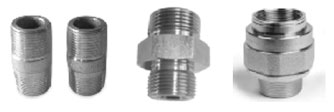
The three piece unions have to be used in hazardous areas, for the junction between conduits pipes and boxes or various appliances. The unions are made up of three independent pieces that can be screwed up by rotating the same pieces among them.
-
Types of Termination Styles
Following are the two types of termination style:
- Metallic Plugs and Socket Connections
- Standard & Miniature Thermocouple Connectors
-
Metallic plug and socket connections
The link between the thermoelectric wires of the thermocouple and those of the extension cable is made by means of non - compensated male and female connectors. The metallic body and casing of these connectors ensure the screening continuity as well as good temperature.
-
Standard and miniature thermocouple connectors
Standard & Miniature connectors are ideal for connecting thermocouple sensors and extension or compensating cable to each other. The pins are polarized to avoid an incorrect connection and the connector body is additionally marked for polarity. These connectors have color coding according to special standard like: ANSI, IEC etc.
-
Pyrometer and its working
A Pyrometer is a non-contacting device that intercepts and measures thermal radiations, without making any contact with the radiating body and the process is known as Pyrometry. This device is useful for determining the temperature of an object’s surface.
Pyrometer strictly works on the principle of black body radiation. Here emissivity of the target plays an important role, as it governs how bright the target appears to the pyrometer. Due to its high accuracy, speed, economy and specific advantages, it is widely being used as a standard procedure in many industrial applications.
Working:
- An optical system gathers the visible and infrared energy from an object and focuses it to the detector.
- The detector receives the photon energy from the optical system and converts it to an electric signal to drive a temperature display or control unit.
-
How to select right Pyrometer for your application?
- Temperature Range:
Basic requirement to choose a pyrometer is to know the temperature range of the application. - Spectral range:
The material of the measured object demands the correct selection of spectral range of pyrometer. - Field of View (D: S ratio):
The larger the measuring distance/spot size (D:S) ratio, the higher the optical resolution. The spot size has to be as big as the measured object to achieve a correct temperature measurement. - Sighting:
For easy focusing of pyrometers to measure object, different sighting system are available i.e. aiming and View finder. - Records of the data:
Data logging and companion software for data storage, retrieval and analysis. - Calibration of Pyrometer:
A Pyrometer should be calibrated at desired temperature ranges.
- Temperature Range:
-
Advantages of online and handheld Pyrometers?
- Ability to monitor temperature in situations where the object is inaccessible or moving.
- Where the object may be contaminated or damaged by a contact sensor.
- Where contact is not possible due to extremely high temperatures, or where the object is electrically active.
- An Infrared Thermometer can be mounted remotely from the hot target, enabling it to operate for long periods with minimal maintenance.
- Lightweight, User Friendly and Compact.
- Very fast response time in tune of msec.
-
Applications of Non-Contact Pyrometers
Pyrometers have wide range of diverse applications in various industries:
- Glass Industries
- Steel Industry
- Cement Industries
- Power Industries
- Non-Ferrous Industries
-
Industrial Heater and its working
Industrial Electric Heaters convert electric energy to heat based on Ohm`s Law. Heat generated is transferred to the load via conduction, convection or radiation. Based on direct resistive heating, this technology is the most beneficial, hence preferred over fuel based heating
Working:
- Industrial heaters works on the principle of ohms law.
- The high resistance wire carrying electrical energy converts the energy into heat energy.
- The heat generated then transferred to load.
-
Applications of Industrial Heaters
The various applications of industrial heaters are:
- Industrial immersion heaters are designed for direct contact heating of water, oils, viscous materials, solvents, process solutions and gases for many industrial heat applications.
- In-Line Heaters are used in Water Heating, Freeze Protection, heat Transfer Oil heating, Fuel Oil Heating, Steam, Air, Gas heating and others variable applications.
- Furnace Heaters generally used for different furnaces applications including Annealing furnaces, galvanizing furnaces etc.
- Component Heaters are used for heat staking, plastic welding, laminating, drying, heat sealing, high temperature or corrosive applications and Critical Nuclear applications.
-
Extension Cable
Extension cable uses wire of nominally the same conductor as the thermocouple itself, which thus inherently possess similar thermo power characteristics, and with no connection problems. Miss-match error arising from high connecting box temperature is likely to be relatively small. These cable are less costly then thermocouple wire, although not cheap, and are usually produced in a convenient form for carrying over long distance typically as flexible wiring or multi-core cables.They are recommended for best accuracy.
-
Compensating Cable
Compensating cable is made of alloys which are different from those of thermocouples but have the same output over a limited temperature range. Compensating cable is a connector between thermocouple and measuring instruments, these cables are less precise, but cheaper. They harness quite different relatively low cost alloy conductor materials, whose net thermocouple in question. The combination develops similar output as those of the thermocouple, but the operating temperature range has to be restricted to keep miss-match error acceptably small.
-
MI Cable and its Construction
MI cable is a sheathed Thermocouple Cable, having an outer sheath of metal with Two to Eight Cores where positive and negative thermo elements run around Circular Pattern, embedded in MgO. Mineral Insulated Cables are suitable to high Mechanical, Chemical, and Electrical stability. Due to good Flexibility, Excellent mechanical strength, and pressure resistance, mineral insulated Thermocouples/RTD`s can be installed in complex installations.
Construction:
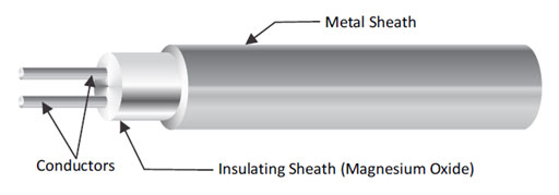
- One or more wire like conductors (cores) are embedded in a high insulation quality MgO(Magnesium Oxide) and pressed into a metal tube (sheath) made of oxidation and corrosion resistant material. The entire combination is then processed using suitable forming steps to obtain the final dimensions.
-
Applications of MI Cables
MI Cables cover up the wide area of applications. Important are listed below:
- In Chemical, Petrochemical and fertilizer industries, and as equipment in dairy, food processing, pharmaceutical industries, in hospitals, households as kitchenware, cryogenic vessels and as heat exchanger in air conditioning refrigeration, for machinery in paper, pulp and textile beverage sector.
- Architectural trims, Marine exteriors, chemical processing equipment, food processing equipment, petroleum refining equipment, photographic equipment.
- Nuclear power and reactor construction, chemical apparatus engineering, annealing furnaces, heat exchangers, crude oil industry, grease and soap industry, aircraft exhaust stacks and manifolds, pressure vessels, large mufflers for diesel engines, carburetors, expansion bellows, stack liners, fire walls etc.
- Power technology, recuperates, heat treatment kilns, vortex firing installations, waste incinerators, furnace construction, boilers and blast furnaces, PWR, Space Travel.
-
Industrial Furnace and its working
Industrial furnaces provide continuous heating to process materials. They are generally built from high temperature (refractory) materials so that they can maintain high temperatures without breaking down. Often, furnaces are set to function for months at a time to complete a processing set.
Working:
- Resistance is the basic electrical principle that explains how heating elements work.
- Heating elements are basically long wires wound into tight coils mounted inside of the furnace cabinet. The resistivity of the wire creates heat as a byproduct.
- Heating starts with the thermostat, which sends an electric signal to relays inside the furnace
- Heating elements usually can't be repaired, but they are replaceable.
-
Applications of Industrial Furnace
There are numerous applications of industrial furnaces viz.
- High temperature furnaces for research, laboratory and production.
- Chamber kilns for daily use in industry, potteries and laboratories for firing ceramics, ceramic precision casting moulds, stoneware, tiles, clay, and soft porcelain.
- Chamber furnaces with air circulation for heat treatment of metals
- Application in pilot plants and laboratories
- Ceramic industry, powder metallurgy, nuclear industry and materials research & development
- Heat treatment for gemstones
- Heat treatment processes such as hardening, brazing, soldering, melting, & levitation melting and gluing.
- Universal drying and heating units for laboratory and production. The furnaces are suitable for general cargos, granules and powder. Wide range of applications in foundry, food, building materials, chemical, pharmaceutical industry and many other industries.
-
Calibration Equipment and its working
Calibration is the comparison of a measuring instrument against an accurate standard to determine any deviation. Calibration equipment is an accurate standard device which is used to check accuracy of the test equipment (Temperature Sensors like thermocouple, RTDs, Pyrometers). Calibration of equipment is done to control errors so that the equipment(Sensor) gives reliable and acceptable measurement.
Working:
- Reference Standard is selected which value is known.
- Measure the test equipment on the basis of reference standard
- A functional relationship is established between measured values and already known values called as calibration curve.
- With reference to this curve the corrections of all measurements are done by taking the inverse of the calibration curve.
-
Application of Calibration Equipment
Calibration equipment is used in calibrating different Temperature units like: RTD, Thermocouple, pyrometer etc. The major applications are in:
- Black body Calibrators are used to minimize the emissivity errors in pyrometer.
- Black Body Furnace is used to calibrate non-contact IR thermometer.
- Reference Units are used in Industries, Laboratories and instrument shop.
- High temperature block furnace is designed for high temperature range calibration and finds application in the glass, electrical, power, automotive & material processing industries and laboratories.
- High Stability Block furnace has been designed for high temperature range calibration and finds application in the glass, electrical power, automotive & material processing industries and laboratories.
- Portable Calibrator is designed for medium range temperature calibration and find applications in the glass, electrical power, automotive and material processing industries.
- Liquid Calibration Bath is used in Laboratory.
-
Furnace TUS and its need
Temperature Uniformity Surveys commonly referred to as a TUS, establish objective evidence of the heat distribution characteristics throughout an oven or furnace system. It also identifies the qualified work zone within the oven or furnace system. TUS's can also be an effective way of determining the efficiency of the furnace system and to monitor furnace performance over time.
System Accuracy Test, commonly referred to as an SAT, is another critically important and often required test. System Accuracy Tests are performed to determine the error within the temperature control system (temperature control device/lead wire/thermocouple). Regardless of the application, knowing the error that exists in your temperature control system allows for more consistent control of quality.
Need of Furnace Calibration
The purpose of the uniformity survey is to determine the range of temperatures present at different locations in the furnace under normal operating conditions standards. It will cater the needs for uniform heating inside the furnace to match the product quality as well as process parameters.
-
Why Calibration is important for your sensors?
- To achieve the highest possible accuracy, a sensor should be calibrated according to the system where it will be used.
- Even in manufacturing, same type of sensors yield slightly different readings from one another. Therefore, calibration is required to identify error.
- The sensor may give different output during storage, shipment, delivery and assembly.
- The sensor may give different output during storage, shipment, delivery and assembly.
- Sensor is subject to heat, shock, cold and humidity and may give a different output which is not acceptable.
- Sensor gets deviate with age which in turn does not give accurate reading. In order to get correct deviation, the sensor should be re-calibrated time-to-time.
-
What is an Accredited Lab?
- It provides the recognition to competent laboratories so that the customers can identify and select the reliable calibration, measurement and testing services for their needs.
- Labs are re-evaluated by accreditation body periodically to ensure that their standard of operation is maintained. The labs may also be required to participate in relevant proficiency testing programs between reassessments, as a further demonstration of technical competence.
- Accredited labs issue a test or calibration reports bearing the accreditation body’s symbol or endorsement, as an indication of their accreditation.
- Clients are encouraged to check the laboratory as to what specific tests or measurements they are accredited for, and for what ranges or uncertainties.
-
Master Sensors
- Industrial thermometers come in a variety of forms and types, calibrating them can be quite complicated.
- To calibrate industrial sensors the laboratory must compare them to standard thermometers whose characteristics have been defined and are traceable to National Standards. Such thermometers that are traceable to national standard are known as 'Master Sensors'.
- Master sensor is used as a reference sensor in comparison type calibration process.
- Master sensor is put in the highly stable temperature zone along with sensor under calibration, their reading is compared and error is calculated.
- Master should have high accuracy, and repeatability and should be recalibrated after certain period of time (generally time period suggested by calibration Laboratories).
-
Cold Junction Compensation
A practical industrial or laboratory Thermocouple consists of only a single (measuring) junction; the reference is always the terminal temperature.
Possible measures are:
- Measures the terminal temperature accurately and compensate accordingly in calculating the measured value.
- Locate the terminals in a thermally controlled enclosure.
- Terminate not in copper cable but use compensating or actual thermocouple wire to extend the sensor termination to the associated instrumentation (compensating cable uses low cost alloys, which have similar thermoelectric properties to the actual thermo element). On this basis, there is no thermal voltage at the thermocouple termination. The transition to copper then occurs only at the instrument terminals where the ambient temperature can measure by the instrument; the reference junction can then be compensated for electronically.
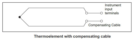
- Use a temperature transmitter at the termination point. This is effectively bringing instrumentationclose to the sensor where electronic reference junction techniques can be utilized. However, this technique is convenient and often used in plant; transmitter produces an amplified (corrected) signal, which can be sent to remote instruments via copper cable of any length.
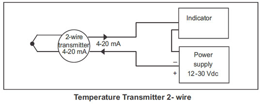
-
What is a Thermal Imager
- A thermal image (Thermogram) is a digital representation of a scene and a measure of the thermal radiation emitted by the pictured objects. Thermal images are captured via thermographic cameras (Thermal Imagers), which are devices capable of sensing this radiation in the form of infrared light.
- A thermal image allows us to remotely sense the temperature of an object or at least accurately tell its temperature relative to its environment. This is useful as it allows us to essentially "see" in the dark as well as perceive the temperatures of many objects remotely.
-
How does the Thermal Camera Work
- Thermal camera uses special sensor to measure the Infra Red energy emitting from any body. As every object in the universe with temperature above Absolute zero -273.15°C emits IR, This can be used to measure temperature of that particular object
-
How does Thermal Camera detect COVID 19 virus.
- Thermal camera is not used to detect the virus, but the Thermal camera measures the temperature of a person's face and let us know if that person is suffering from fever or not. As Fever is a symptom for the virus, that person can be isolated and sent for further medical diagnosis.
-
Can I use Thermal Camera to see through walls.
- No Thermal Imaging camera works on the Infra Red spectrum, and it will only see through objects which are transparent in IR range like Germanium, ZnSe etc. A brick wall will not be transparent and hence thermal cameras cannot see through walls.