- Home
- About
- Products
- Contact Temperature Sensors
- Cables & Wires
- Mineral Insulated Cables
- Nickel & Thermocouple Alloy
- Industrial Heaters
- Heating Cables and Mats
- Non Contact Temperature Sensors
- Industrial and R&D Furnaces
- Temperature Calibrators
-
Circulating Chiller
- Services
-
Special Products
- Thermal Profiling System
- Industries
- Resources
- Contact Us
- Shop
Search
RTD (Resistance Temperature Detectors)
RTD’s are temperature measuring sensors which uses resistance /temperature relationship of a material to measure temperature of a body. The sensor element is made up of pure materials such as Platinum, Nickel and Copper. RTD’s have higher accuracy and stability as compared to Thermocouples usually in the below 600 °C range.
Resistance/Temperature Relationship:
The Resistance vs Temperature relationship is stated as the amount of change in the resistance of the element per degree change in temperature. This relative change in resistance is called Temperature Coefficient of Resistance (α) and this remains nearly constant throughout the temperature range of the sensor.
Platinum is the most preferred material for RTD sensors as unlike other elements it possesses highly linear Resistance – Temperature relationship which is repeatable within a wide temperature range. This linear temperature ranges from (-272.5) °C – (961.78) °C. Platinum is also preferred due to its chemical inertness which makes it ideal to use under any environment.
The sensors made for the International Temperature Scale standard (ITS-90) are also Platinum sensors.
Copper also has a good linear Resistance – Temperature relationship but it oxidizes above 150°C, which makes it unreliable for higher temperatures.
Nickel shows a Non-Linear relationship above 300 °C which limits its temperature range.
The linear approximation of resistance vs temperature is taken between 0 °C – 100 °C.
α = (R100 – R0)/ (R0 x ΔT)
Where,
R100 is the resistance of the sensor at 100 °C
R0 is the resistance of the sensor at 0 °C
ΔT is the temperature difference
Pure Platinum has α= 0.003925 Ω/ (Ω·°C) for 0 – 100 °C range.
But the acceptable value specified by IEC 60751 and ASTM E-1137 Standards is
α = 0.00385 Ω/ (Ω·°C)
The value of α is varied by a process called doping in which impurities are fused into the molecular lattice of Platinum in a controlled fashion.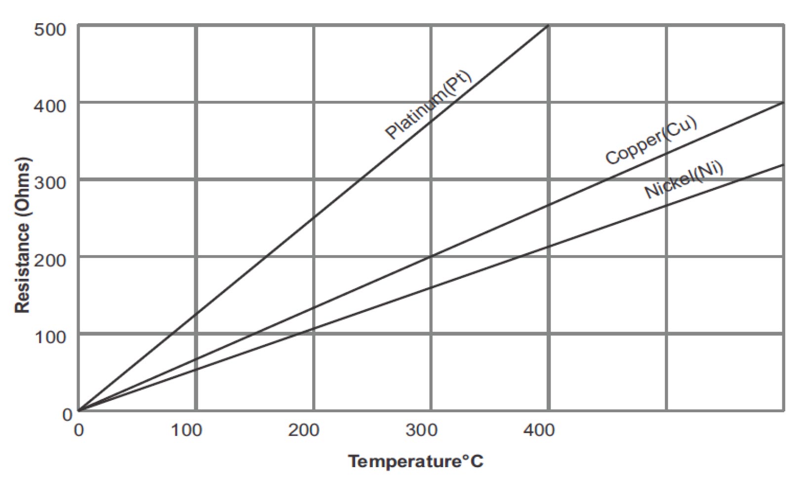
RTD elements are also available with resistances 200, 500 and 1000 Ω at 0°C. Such type of RTDs are known as PT200, PT500 and PT1000 respectively. The temperature coefficients of these types are also same as the PT100, but these provide higher resistance change per degree Celsius which in turn gives higher resolution.
Types of RTD Elements:
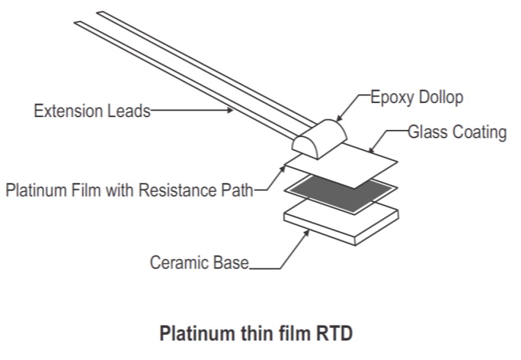
- Thin Film RTD: This type of RTD is the most commonly used one which is due to the rugged design and cost-effectiveness. This thin film element is manufactured by coating a small ceramic chip with a very thin (0.0001”) film of platinum and then laser cutting or chemical etching a resistance path in the platinum film. This is then coated with a thin layer of glass to protect it from external These sensors are less stable than other types.
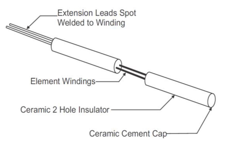
- Coiled RTD: This type of RTD element is usually made from platinum wire. Ultra-thin platinum wire (20 microns) is coiled and then is place inside double holed ceramic insulators. Extension leads are spot welded onto the ends of the platinum wire and then the assembly is cemented in place. These types of RTDs provide the highest accuracy but are not suitable for harsh conditions.
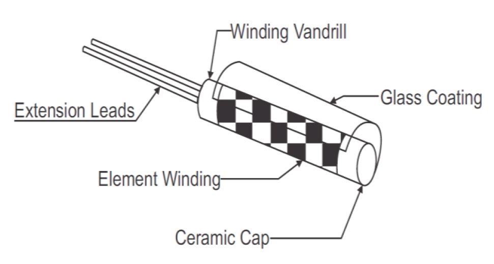
- Wire-Wound RTD: This type of RTD element is manufactured by winding the element wire around a center mandrill, which is usually made of ceramic. The winding is then coated with glass or some other insulating material to protect and secure the windings. The winding wires are then spot welded to extension leads and secured to the body with ceramic cement or epoxy
RTD Classes & Standards:
- Class A: This is considered to have high accuracy and has an ice pointtolerance of ±0.06 ohms.
- Class B: This has a lower accuracy and an ice mantle tolerance of ±0.12 ohms.
The accuracy of an RTD decreases with increase in temperature.
There are two standards for Platinum
- European Standard or DIN / IEC standard
- American Standard
The European standard or the DIN standard is considered as the world-wide standard for Platinum RTDs.
This standard is also called DIN/IEC 60751 It states that the electrical resistance of a RTD should be 100.00 Ω at 0°C and the temperature coefficient of Resistance should be 0.00385 Ω/ Ω/°C between 0 to 100°C
Other Standards for PT100RTDs:
| Standard | R100/R0 Ratio |
| Din 43760 | 1.385 |
| U.S Lap Spec | 1.3926 |
| U.S Industrial Spec. | 1.3911 |
| Canadian Spec. | 1.3889 |
| Mil - T-24388 | 1.3924 |
| Japanese JIS C 1604 | 1.3916 |
- Platinum Resistance Temperature Sensors (PRT) offer excellent accuracy over a wide temperature range from -200 to 850°C.
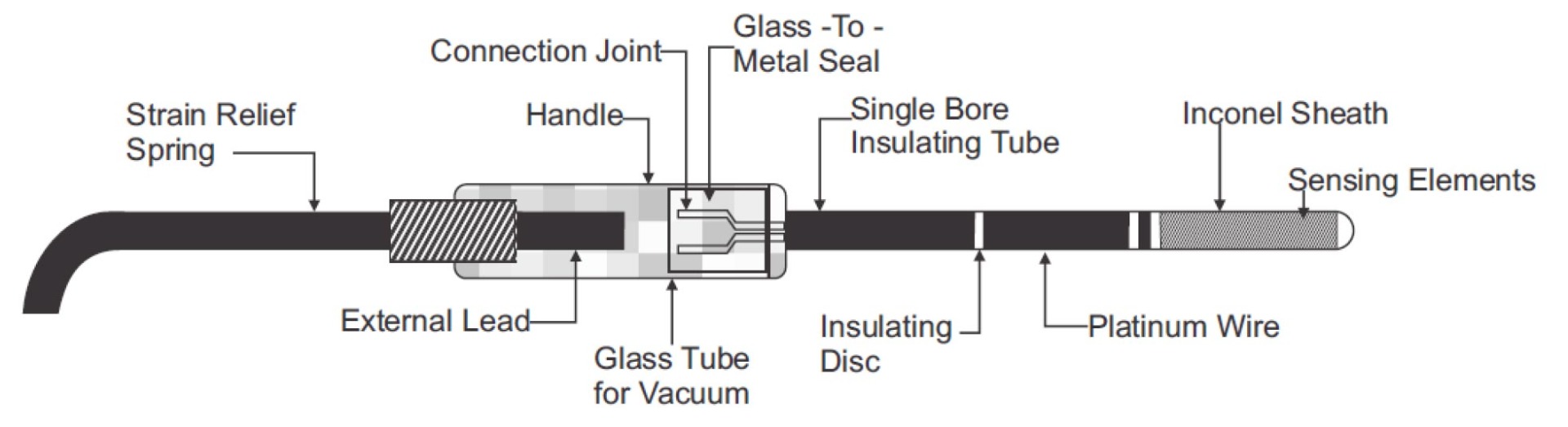
- Standard Platinum RTD (SPRT): These are special set of PRTs which are used to perform the interpolation according to the International Temperature Scale of 1990(ITS-90) fixed reference points which ranges from 13.8033K (Triple point of Hydrogen) to 1244.93K (Freezing point ofsilver).
Lead Wire Configurations:
RTDs are available with 3 different lead wire configurations.
Two wire RTD:
The two wire RTD is the simplest wire configuration. One wire is attached to each side of the element. A measure can be taken by any device equipped to measure resistance, including basic Volt Ohm Meters (VOM). However this is the least accurate way of measuring temperature due the fact that the lead wire resistance is in series with the sensing element. The longer the lead wire greater will be the effect on resistance.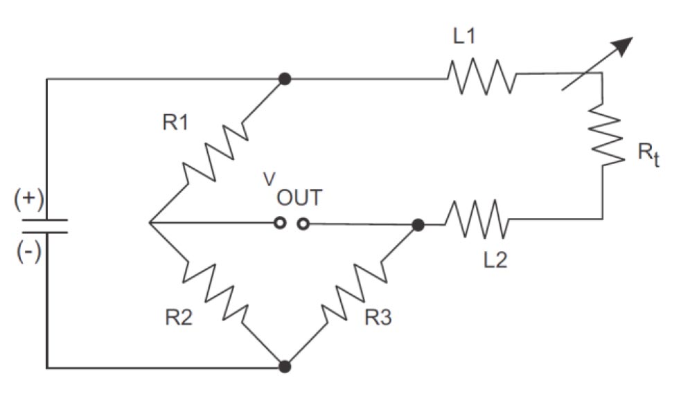
Three Wire RTD:
This is the most popular configuration for use in industrial applications. In order to minimize the effects of the lead resistances, a three wire configuration can be used. Using this the two leads of the sensor are on the adjoining arms. There is a lead resistance in each arm of the bridge so that the resistance is cancelled out, so long as the two lead resistances are accurately the same. This configuration allows upto 600 m of cable.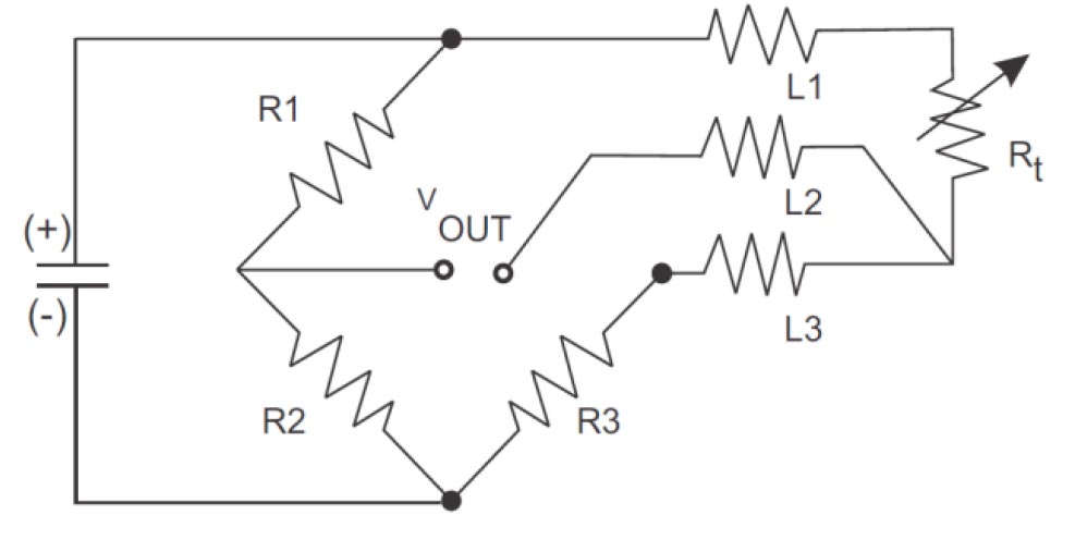
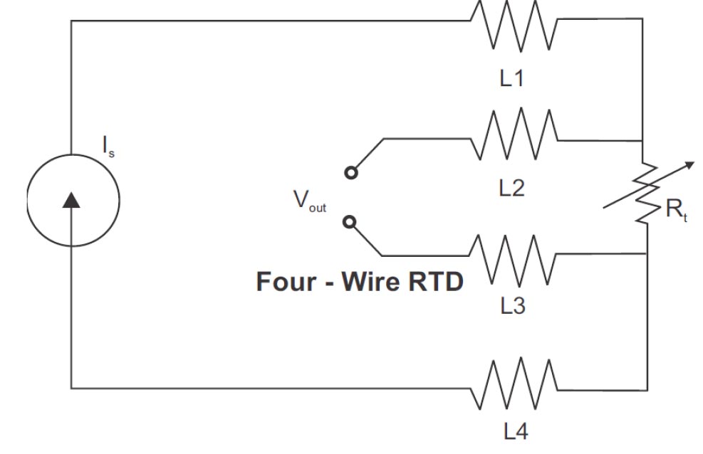
Four Wire RTD:
This is the most accurate method for measuring Resistance of a RTD. It is mostly used in Precision Laboratories and is seldom used in industries. This configuration increases the accuracy and reliability of the resistance being measured, the resistance due the lead wire in this case is null.This RTD circuit removes the effect of mismatched resistances on the lead wires. A constant current is passed through L1 and L4, L2 and L3 measure the voltage drop across the RTD element. The color code for this configuration is 2 red and 2 white wires.