

- Home
- About
- Products
- Contact Temperature Sensors
- Cables & Wires
- Mineral Insulated Cables
- Nickel & Thermocouple Alloy
- Industrial Heaters
- Heating Cables and Mats
- Non Contact Temperature Sensors
- Industrial and R&D Furnaces
- Temperature Calibrators
-
Circulating Chiller
- Services
-
Special Products
- Thermal Profiling System
- Industries
- Resources
- Contact Us
- Shop
Search
Fundamental of Thermocouples
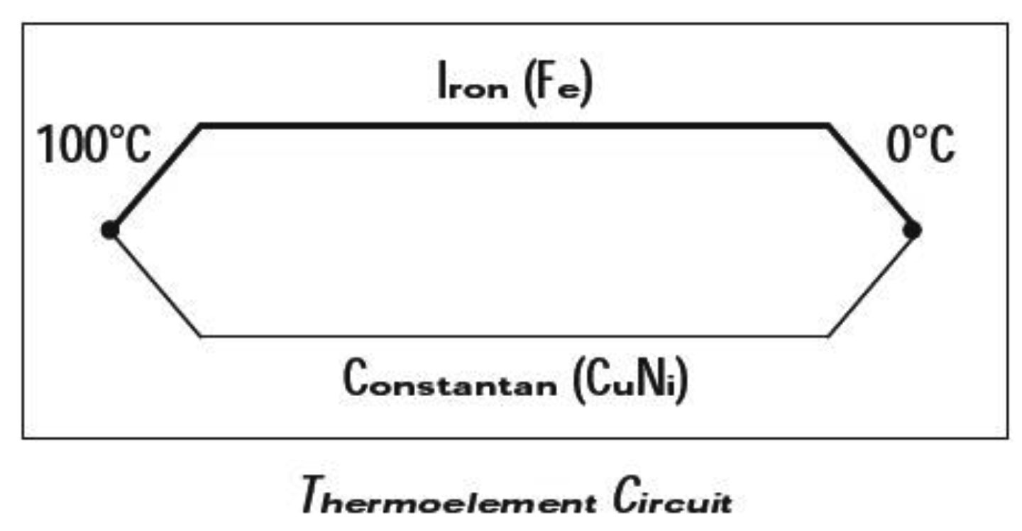
In 1821 a German physicist named Seeback discovered the thermoelectric effect, which forms the basis of modern thermocouple technology. He observed that an electric current flows in a closed circuit of two dissimilar metals if their two junctions are at different temperatures. The thermoelectric voltage produced depends on the metals used and on the temperature relationship between the junctions. If the same temperature exists at the two junctions, the voltage produced at each junction cancel each other out and no current flows in the circuit. With different temperatures at each junction, different voltages are produced and current flows in the circuit. A Thermocouple can therefore only measure temperature differences between the two junctions.
It is important to designate each of the junctions for practical purposes; the measuring junction (often referred to as the 'hot junction) is that which is exposed to be measured temperature. The reference junction is the other junction that is kept at a known temperature; this is often referred to as the 'cold' junction. The term thermocouple refers to the complete system for producing thermal voltages and generally implies an actual assembly (i.e. a sheathed device with extension leads or terminal blocks).
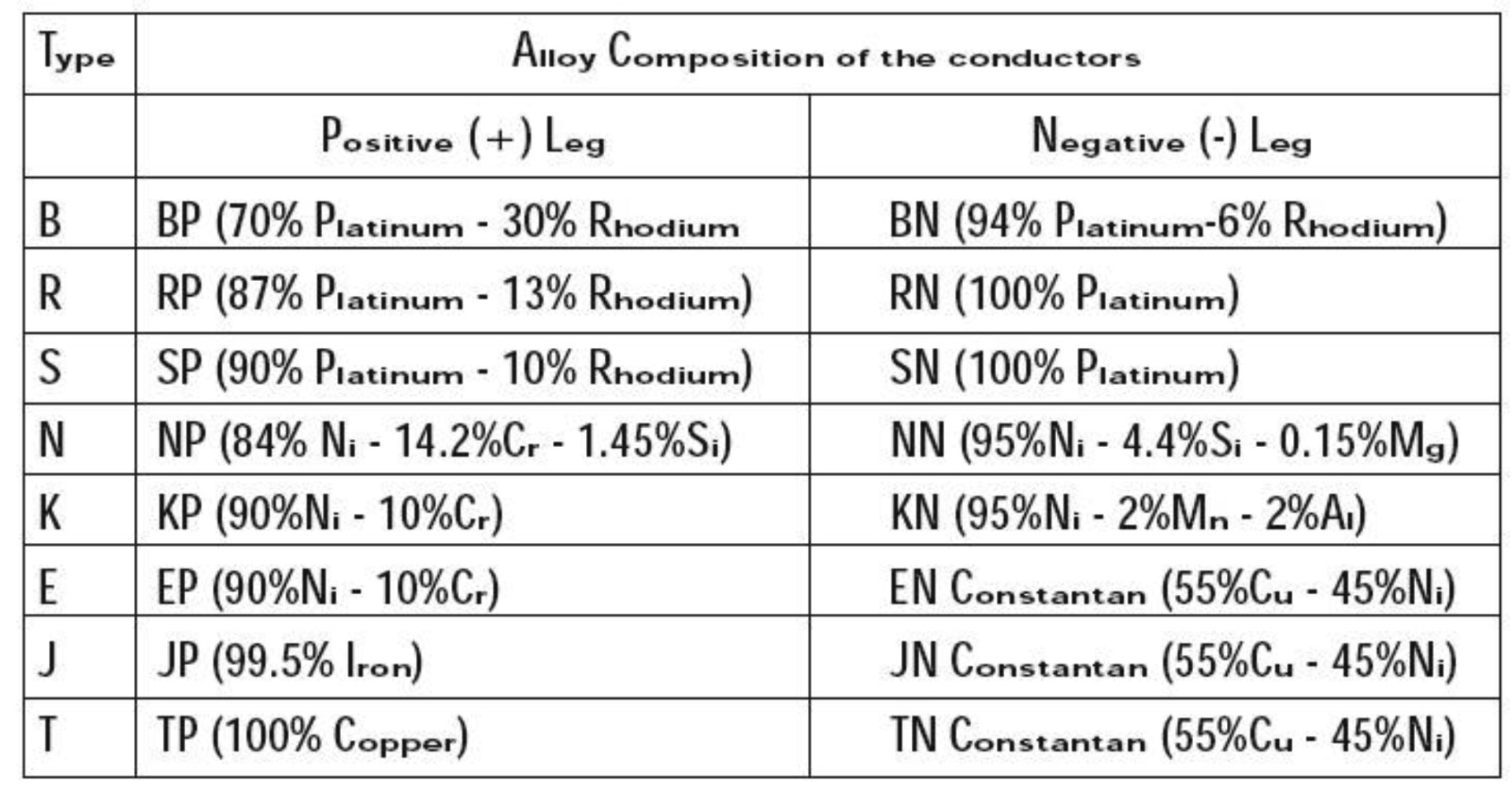
The two conductors and associated measuring junction constitute a thermoelement and the individual conductors are identified as the positive or negative leg.
Developments in theoretical aspects of thermoelectricity under the influence of solid-state physics have resulted in a rather different explanation of thermocouple activity. This is that the thermo electric voltage is generated in the thermocouple wires only in the temperature gradient existing between the 'hot' and 'cold' junctions and not in the junctions themselves. While this is a fundamental conceptual difference to the established theory, the way in which thermocouple are currently used is generally successful in practical terms. However, this explanation of thermocouple behavior must be born in mind when calibrating the sensor or indeed when using it for relatively high precision thermometry.
Thermo electric voltages are very small and at best attain a few tens of micro Volts per degree centigrade. In consequence, practical thermocouple are mainly used at elevated temperatures, above say 100°C and at depressed temperatures, below - 50°C; however with appropriate measuring instrument they can be used at any value with in their operational range. In some application, the reference junction may be held at some temperature other than 0°C, for example in liquid gas or a heated enclosure; in any event, the measured ''output'' will correspond to the difference temperature between two junctions.
Note:- Thermocouple is always formed when two metals are connected together. For example, when the Thermo element conductors are joined to copper cable or terminals, thermal voltages can be generated at the transition. In this case, the second junction can be taken as located at the connection point (assuming the two connections to be thermally common). The temperature of this connection point (terminal temperature) if known, allows computation of the temperature at the measuring junction. The thermal voltage resulting from the terminal temperature is added to the measured voltage and their sum corresponds to the thermal voltage against a 0°C reference.
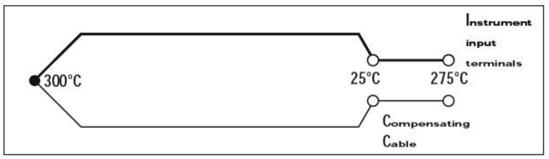
If the measuring junction is at 300°Cand the terminal temperature is 25°C, the measured thermal voltage for the type K thermo element (Nickel-Chromium v Nickel-Aluminium) is 11.18 mV. This corresponds to 275°C difference temperature. Therefore a positive correction of 25°C refers the temperature to 0°C reference; 300°C is thus indicated. Important points to note at this stage are four-fold. Firstly, thermocouples only generate an output in the regions where the temperature gradient exist- not beyond. Secondly, accuracy and stability can only be assured if the thermoelectric characteristics of the thermocouple conductors are uniform throughout. Thirdly, only a circuit comprising dissimilar materials in a temperature gradient generates an output. And, fourthly, although the thermoelectric effects are seen at junctions, they are not due to any
Terminating The Thermocouple :
A practical industrial or laboratory Thermocouple consists of only a single (measuring) junction; the reference is always the terminal temperature. If the terminal temperature is other than controlled and stable, procedures are necessary to deal with the situation. Possible measures area) Measures the terminal temperature accurately and compensate accordingly in calculating the measured value. b) Locate the terminals in a thermally controlled enclosure. c) Terminate not in copper cable but use compensating or actual thermocouple wire to extend the sensor termination to the associated instrumentation (compensating cable uses low cost alloys, which have similar thermoelectric properties to the actual thermoelement). On this basis, there is no thermal voltage at the thermocouple termination. The transition to copper then occurs only at the instrument terminals where the ambient temperature can measure by the instrument; the reference junction can then be compensated for electronically.
Note- It is essential to use only compensating or specific extension cables (these have the correct thermoelectric properties) appropriate to the thermocouple other wise an additional thermocouple is formed at the connection point. The reference junction is formed where the compensating or extension cable is connected to a difference material. The cable used must not be extended with copper or with compensating cable of a different type.
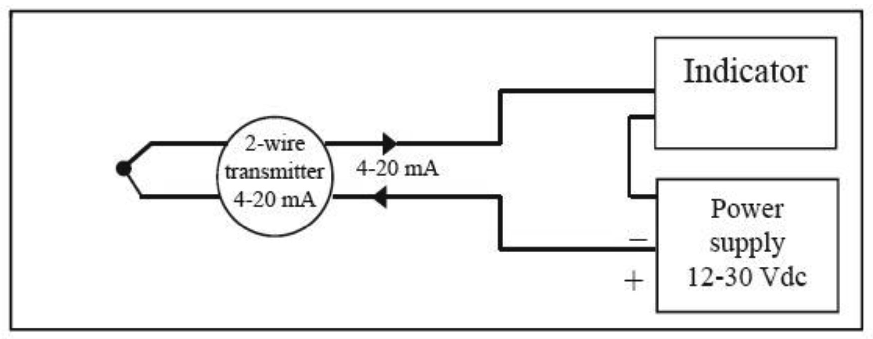
d) Use a temperature transmitter at the termination point. This is effectively bringing instrumentation close to the sensor where electronic reference junction techniques can be utilized. However, this technique is convenient and often used in plant; transmitter produces an amplified ''corrected' signal, which can be sent to remote instruments via copper cable of any length.
Sheathed Thermocouple Measuring Junction
Many alternative sheath materials are used to protect thermo elements and some example is indicated in a separate chapter.
Additionally, three alternative tip configurations are usually offered.
- An exposed junction is recommended for the measurement of following or static noncorrosive gas temperature when the greatest sensitivity and quickest response is required. In this type measuring wires are unprotected & response time is vary fast.
- An Ungrounded (insulated) junction is more suitable for corrosive media although the thermal response is slower due to the air gap between junction and outer sheath. This type of construction provides best protection to thermocouple wires & it is electronically isolated construction. In some applications where more then one thermocouple connects to the associated Instrumentation, insulation may be essential to avoid spurious signals occurring in the measuring circuits.
- An earthed (grounded) junction is also suitable for corrosive media and for high-pressure applications. It provides faster response than the insulated junction and protection not afforded by the exposed junction.
Formation Of The Hot Junction
To form the hot junction, a suitable method has to be adopted to obtain a good electrical contact between the thermocouple wires. At low temperatures, where generally Copper/Copper-nickel couples are used, soft or silver soldering can be adopted.
For Chromal/Alumal and other combinations, for use in high temperature measurements, welding is the only method to obtain a suitable joint. For this purpose oxy-acetylene welding is mostly used, but arc welding also gives good results.
Oxy-acetylene And Gas Welding
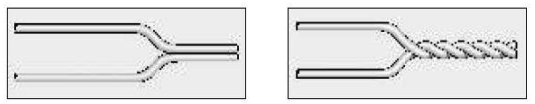
The wire ends have to be cleaned by filing or grinding and twisted together with two or three turns as shown in the picture. This procedure provides a good contact during welding and prevents any tension in the welded joint. The wires are held vertically in a vice and the flame positioned downwards on to the twisted wires for welding. A small drop fusing the wire together at the twisted end forms a good weld. The size of the gas flame must be altered depending upon the wire diameter and it is necessary to use a neutral or reducing flame. Overheating should be avoided as this may cause embitterment of the wires.
With experience, satisfactory welding can be achieved without the use of a flux but if difficulty occurs then borax can be used. Remember that it should be totally cleaned from the metal after the weld has cooled down. Rewelding is difficult. If the weld is inadequate it is usually necessary to cut the wires and start a new weld.
The wires are cleaned and twisted as in gas welding and are then held in a vice, which is connected to a +ve arm of a D.C. Supply. A carbon electrode as the - ve leg is then touched on the twisted wires just sufficiently to create an arc and weld the wires at the end.
The required voltage depends upon the wire diameter but for 3.2 mm diameter a voltage of about 40V is required. No flux is required in this type of welding.
When a Tungsten electrode replaces the carbon electrode, we have a TIG (Tungsten Inert Gas) weld which is also very common for welding thermocouple materials. In this case, a stream of inert gas is blown on to the welding joint to provide full protection against air contamination.
Discharge Capacity Welding
This method of welding is adopted for small diameter wires (up to 0.8 mm). The ends of the thermo element have to be cleaned with emery paper and the wires are held in contact.
TYPES OF THERMOCOUPLE CONSTRUCTION:
There are two types of thermocouple construction is most commonly used.
Mineral Insulated (M.I.) Thermocouples & Non M.I. Thermocouples
Mineral Insulated Thermocouples:
Mineral insulated Thermocouples consist of thermocouple wire embedded in a densely packed refractory oxide powder insulate all enclosed in a seamless, drawn metal sheath (usually stainless steel). Effectively the thermoelement, insulation and sheath are combined as a flexible cable, which is available in different diameters, usually from 0.75mm to 8mm. At one end cores and sheath are welded and from a ''hot '' junction. At the other end, the thermocouple is connected to a ''transition'' of extension wires, connecting head or connector.
Advantages of mineral insulated thermocouple are :-
- Small over all dimensions and high flexibility, which enable temperature measurement in locations with poor accessibility.
- Good mechanical strength
- Protection of the thermoelement wires against oxidation, corrosion, and contamination.
- Fast thermal response
The mineral oxides used for insulation are highly hygroscopic and open-ended cables must be effectively sealed (usually with epoxy resins) to prevent moisture take-up. A carefully prepared mineral insulated thermocouple will normally have a high value of insulation resistance (many hundreds of mega ohms).
Non M.i. Thermocouples
In Non-M.I. thermocouples, thermocouple wires are either insulated with ceramic beads or after insulation of ceramic, covered by a metal sheath (usually stainless steel) and some form of termination (extension lead, connecting head or connector for example) is provided. In this type of construction thermocouple wires are protected from the measuring environment when a sheath protection is provided. The sheath material is dependent on the measuring environment usually stainless steel is used. According to the corrosive environment sheath selection is changed. This construction does not provide flexibility & not found in small sizes. Not too good mechanical strength. In Non M.I. construction sheath may be of ceramic or metal as per suitability. Exposed, Grounded and Ungrounded all types of junctions are formed in both the M.I, & Non M.I. construction.
Thermocouple Types:
Many combinations of materials have been used to produce acceptable thermocouples, each with its own particular application spectrum. However, the value of interchangeability and the economics of mass production have led to standardization, with a few specific types now being easily available, and covering by far the majority of the temperature and environmental applications. These thermocouples are made to conform to an e.m.f/ temperature relationship specified in the form of tabulated values of e.m.fs resolved normally to 1mV against temperature in 1C intervals, and vice versa. Internationally, these reference tables are published as IEC 584 1,2 & 4, which is based on the International Practical Temperature Scale ITS-90. It is worth noting here, however, that the standards do not address the construction, or insulation of the cables themselves or other performance criteria. With the diversity to be found, manufacturers' own standards must be relied upon in this respect.
The standard covers the eight specified and most commonly used thermocouples, referring to their internationally recognized alpha character type designation & providing the full reference tables for each. These thermocouple types can be subdivided in 2 groups, base metal & noble (rare) metal.
At this point, it is worth looking at each in turn, assessing its value, its properties and its applicational spread. Note that the positive element is always referred to first. Note also that, especially for base metal thermocouples, the maximum operating temperature specified is not the be all and end all. In the real world, it has to be related to the wire diameter- as well as the anticipated environment and the thermocouple life requirements.
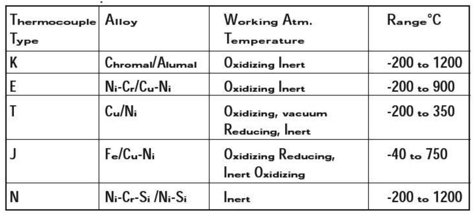
Base Metal Thermocouples -200°c Up To 1200°c These Thermocouples Use Base Metals
-
Type K (Ni-Cr/Ni-Al) Thermocouples :
Type K thermocouple was originally developed by Mr. A. L. Marsh of Hoskins Co., U.S.A. in 1906 and, since then it has undergone many improvements. It has linear EMF characteristics with sensitivity of 41V/°C and are most widely used as industrial thermocouple with high reliability because of its versatile characteristics. It can be used in oxidizing or inert atmospheres at temperatures up to 1250°C.
Type K thermocouple may be used in hydrogen or cracked ammonia atmospheres if the dewpoint is below -42°C. However, it should not be used in reducing, alternatively oxidizing and reducing, sulfurous or "greenrot" corrosive atmospheres unless properly protected.
"Green-rot" can be minimized by increasing oxygen supply through the use of large diameter protection tube or ventilated protection tube. It can also be minimized by inserting a "getter" to absorb the oxygen in a sealed protection tube. Although type K is widely used because of its range and cheapness, it is not as stable as other base metal sensors in common use. At temperature between 250°C and 600°C and especially between 300°C and 550°C, temperature cycling hysteresis can result in errors of several degrees. Again, although Type K is popular for nuclear applications because of its relative radiation hardness, Type N is now a far better bet.
-
Type J (Iron/Constantan) Thermocouple :
Type J thermocouple has the second highest EMF characteristics it is recognized as more stable than Type K, It is therefore more suitable for accurate measurement with a sensitivity of 55V/°C and is recommended for use in reducing, inert, oxidizing or vacuum atmospheres upto 750°C. Because of comparatively less expensive price, type J has been easily accepted for use in various applications. However, it should not be used in sulphurous atmospheres above 538°C due to formation of the sulfides that leads conductors to embrittlement. The iron element is often rusted under high humidity environment, therefore, type J is less desirable than type T for low temperature measurements.
-
Type E (Ni-Cr/Constantan) Thermocouple :
Type E thermocouple has the highest EMF characteristics with sensitivity of 68V/°C among industrial thermocouples which allows the best resolution to temperature change.
Since it was adopted by ANSI in 1964 and JIS in 1974, type E thermocouple has met rapidly increasing demands and has been widely used even in large scale thermal and nuclear power stations. It can be used up to 750°C continuously. For practical use, precautions similar to those for type K are required. Careful attention is also needed in selection of the indicator to be connected because type E thermocouple has the highest resistivity among the base metal thermocouples.
-
Type N (Nicorsil/Nisil) Thermocouple:
This new thermocouple which is combination of 84%Ni-14.2%Cr-1.14%Si Vs. 95.5%Ni-4.4%Si-0.1%Mg was first developed by Materials Research Laboratory of the Australian Department of Defense. Further research and evaluation have been extensively carried out by NIST (former NBS), ASTM and other research organizations to standardize and establish the present EMF table. Type N thermocouple exhibits superior long-term stability and oxidation resistance over type K when used at high temperatures ranging from 600 to 1250°C By virtue of fine adjustment of chromium content with additions of Si and Mg, it has less EMF shift in the region of "short range ordering" and also resistant to "Green Rot" corrosion. In comparison with type K, rate of EMF drift is reported to be half or one third over the range of 1000°C and sensitivity is 39V/°C, therefore recommended for use in oxidizing atmosphere of 1000-1200°C continuous.
-
Type T (Copper/Constantan) Thermocouple:
Copper- Constantan, its original name, has found quite a niche for itself in laboratory temperature measurement over the range 250°C to 400°C although above this the copper arm rapidly oxidizes. Repeatability is excellent in the range -200°Cto 200°C (±0.1°C).
Type T thermocouple has good resistance to corrosion in moist atmospheres and is suitable for sub-zero temperature measurements. It can be used in vacuum and in oxidizing, reducing or inert atmospheres up to 400°C, At higher temperatures, it is susceptible to rapid oxidation by water vapour, Because of its stable and precise EMF characteristics, Type T is widely used in laboratories but the e.m.f/ temperature curve quite nonlinear especially around 0°C and sensitivity is 42V/°C. Type T is the first thermocouple for which tolerance in the subzero temperature range has been established. Due to high thermal conductivity of the conductors, care must be exercised to eliminate heat conduction error that offen occur on short stem length type T thermocouple unit.
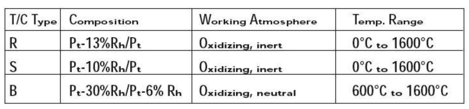
Noble Metal Thermocouples
0°C up to 1600°C. These thermocouples uses noble Metal (Platinum- Rhodium)
2.1 Type S (Pt-10%Rh/Pt) Thermocouple :
Type S thermocouples is the First historic thermocouple originally developed by Le Chatelier in 1886. This thermocouple, can be used in oxidizing or inert atmospheres continuously at temperatures up to 1600°C and for brief periods up to 1700°C. for high temperature work, insulators and sheaths made from high purity recrystallised alumina are used. In fact, in all but the cleanest of applications, the device needs protection in the form of an impervious sheath since small quantities of metallic vapour can cause deterioration and a reduction in the e.m.f generated.
Continuous use at high temperatures also causes degradation, and there is possibility of diffusion of rhodium in to the pure platinum conductoragain leading to a reduction in output. Sensitivity lies in between 6 and 12V/°C
2.2 Type R (Pt-10%Rh/Pt) Thermocouple :
Type R thermocouple has superior mechanical properties to Type S and is recommended for continuous use in oxidizing and inert atmospheres around temperatures up to 1400°C and intermittently up to 1600°C. However, it should not be used in vacuum, reducing or metallic vapour atmospheres unless properly protected with clean high purity (>99.5%) Alumina insulators and protection tubes. This thermocouple has the advantage of slightly higher output and improved stability. Among precious metal thermocouples, Type R is most widely used and are preferred over Type S while the application covered are broadly identical. The sensitivity of Type R lies in between 6-14V/°C
2.3 Type B (Pt-30% Rh/Pt-6%Rh) Thermocouple :
Type B thermocouple has higher melting point and mechanical strength than other Pt/Rh thermocouples because of its higher content of Rhodium in both legs. Type B thermocouple can be used continuously in oxidizing and neutral atmospheres up to 1600°C and intermittently up to 1700°C. Even in reducing atmosphere, Type B may be used for fairly longer period than other Pt/Rh thermocouples, but not generally recommended.
Type B thermocouple is recommended especially for the applications requiring precision measurement and durability at high temperatures. This thermocouple has very small EMF up to 100°C, thus for less critical applications, copper leads can be used as a compensating wire. An interesting practical advantage is that since the output is negligible over the print of 0°C to 50°C, cold junction compensation is not normally required. Precious metal thermocouples are generally sensitive to contaminants and easily be corroded at elevated temperatures. It is essential to keep the thermocouple wire clean and use dust free high purity (>99.5%) Alumina insulators and protection tubes.
Additionally there are specialized thermocouple types, which are not described here; these include Tungsten Rhenium types, Pallaplat, Nickel Molybdenum and other platinum Rhodium alloys.
Combination Of Standardized Thermocouples
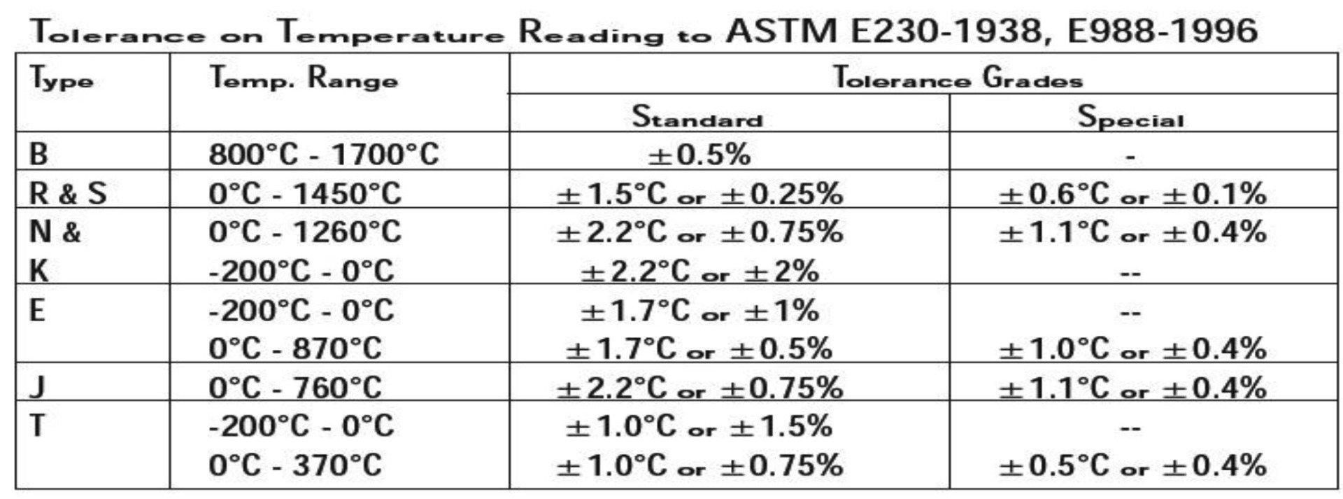
Tolerances On Temperature Reading :
Tolerance Denotes the maximum allowable value obtained by subtracting the temperature reading or the temperature at the hot junction from the standard temperature converted from the applicable temperature EMF table. JIS C1602-1995 IEC 584-2-1982 (Amendment 1-1989) BS/EN 60584-2-1993 DIN/IEC 584-2-1992
Maximum Operating Temperature
Operating temperature limit means the upper temperature where thermocouple can be used continuously in air. Maximum limit means the upper temperature where thermocouple can be used temporarily for short period of time owing to unavoidable circumstances. This graph is given as a guide only, and not to be guaranteed.
Principal factors that affect the life of a thermocouple are:
- Temperature: Thermocouple life decreases by about 50% when an increase of 50 °C occurs.
- Diameter: By doubling the diameter of the wire, the life increases by 2-3 times.
- Thermic cycling: When thermocouples are exposed to thermic cycling from room temperature to above 500 °C, their life decreases by about 50% compared to a couple used continuously at the same temperature.
- Protection: When thermocouples are covered by a protective sheath and placed into ceramic insulators, their life is considerably extended.
Accuracy And Response:
High Accuracy Thermocouple Measurement
With thermocouple tolerance quoted at say ±2.5°C plus other variations it would appear a poor case made for high accuracy thermocouple measurement, for example in research and high industrial technology, the key to accuracy in this field lies in the careful selection of method and material, and the heat treatment and calibration of the thermocouples. While application conditions do alter techniques, the following factors are suggested for consideration.
- Obtain thermocouples with insulated measuring junctions.
- Specify "same metal" for large installation, preferably close tolerance.
- Thermocouple reference junction should be monitored in a reference unit with an accuracy of +0.1°C or better.
- Great care to be taken in running thermocouple circuitry against ''Pickup'' etc. with the minimum number of joints in the wiring.
- Heat-treat thermocouple to their most stable condition.
- Calibrate thermocouples.
Thermocouple Response Times
The response time for a thermocouple is usually defined as the time taken for the thermal voltage (output) to reach 63% of maximum for the step change temperature in question. It is dependent on several parameters including the thermocouple dimension, construction, tip configuration and the nature of the medium in which the sensor is located. If the thermocouple is plunged in to a medium with a high thermal capacity and heat transfer is rapid, the effective response time will be practically the same as for the thermocouple itself (the intrinsic response time). However, if the thermal properties of the medium are poor (e.g. still air) the response time can be 100 times greater.
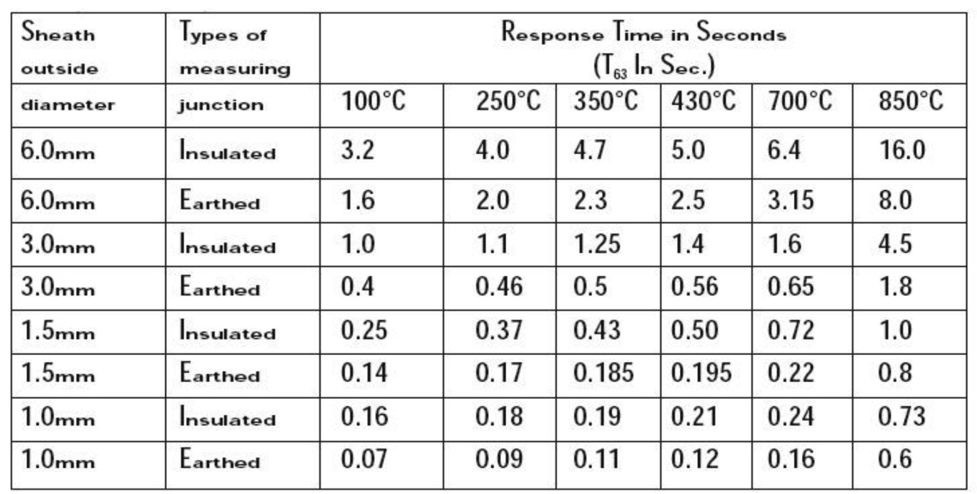
- Values shown are for a closed end sheath.
- For exposed measuring junctions, divided the values shown by 10.
- Thermocouple with grounded junction display response times some 20 to 30% faster than those with insulated junction.
- Very good sensitivity is provided by fine gauge unsheathed thermocouples. With conductor diameter in the range 0.025mm to 0.81mm, response times in the region of 0.05to 0.40 seconds can be realized.
Immersion Length
Thermocouple assemblies are'' tip'' sensing devices which lends them to both surface and immersion applications depending on their construction. However immersion type must be used carefully to avoid error due to steam conduction; this is heat flow to or from the sheath and in to or away; from the process which can result in a high or low reading respectively. A general rule is to immerse into the medium to a minimum of 4 times the out side diameter of the sheath; no quantitative data applies but care must be exercised in order to obtain meaningful results.
The ideal immersion depth can be achieved in practice by moving the probe in to or out of the process medium incrementally;
with each adjustment, not any apparent change in indicating temperature. The correct depth will result in no change in indicating temperature.
Surface Temperature Measurement
Although thermocouple assemblies are primarily tip sensing devices, the use of protection tubes renders surface sensing impractical. Physically, the probe does not lend it self to surface presentation and steam conduction would cause reading errors. If thermocouple is to be used reliably for surface sensing, it must be either exposed, welded junction from with very small thermal mass or be housed in a construction, which permits true surface contact whilst attaching to the surface. Locating a thermocouple on a surface can be achieved in various ways including the use of an adhesive path, a washer and stud, a magnet for ferrous metal and pipe clips.
Advantage Of Thermocouple
Industrial thermocouple, in comparison with other thermometers, has the following features:
- Quick response and stable temperature measurement by direct contact with the measuring object.
- It the selection of a quality thermocouple is properly made, wide range of temperature can be measured.
- Temperature of specific spot or small space can be measured.
- Since temperature is detected by means of EMF generated, measurement, adjustment, amplification, control, conversion and other data processing are easy.
- Less expensive and better interchangeability in comparison with other temperature sensors.
- The most versatile and safe for measuring environments, if a suitable protection tube is employed.
- Rugged construction and easy installation.