

- Home
- About
- Products
- Contact Temperature Sensors
- Cables & Wires
- Mineral Insulated Cables
- Nickel & Thermocouple Alloy
- Industrial Heaters
- Heating Cables and Mats
- Non Contact Temperature Sensors
- Industrial and R&D Furnaces
- Temperature Calibrators
-
Circulating Chiller
- Services
-
Special Products
- Thermal Profiling System
- Industries
- Resources
- Contact Us
- Shop
Search
Sheath materials, Thermowells,Fittings, and Terminations
Temperature sensor element for laboratory and industrial use should normally be protected by some form of sheath or housing. There are a wide range of installation fitting and accessories which are available to facilitate installation in the actual process and to permit convenient interconnection with instruments.
Constrution
-
Industrial Temperature Probe
The illustration of the assembly is identical for both Pt100 and thermocouple sensor. The protection tube or sheath, houses the thermocouple or Pt100 either directly or indirect via an insert. Additionally a thermo well may be utilized for purposes of installi ng the probe into the process or application.
Sensor inserts are fabricated unit which is comprised by a sensor and a terminal base; the sensor is housed in a stainless steel insert tube, usually of 6 or 8mm diameter and, then it is inserted into the actual protection tube. Good sheathing with physical contact between the insert tip and sheath end is essential to ensure good heat transfer. Spring contact is used in the terminal base to maintain this contact. This arrangement facilitates easy replacement of the sensor whenever required. In the case of a mineral insulated thermocouple or Pt100, the sensor is designed as an integral part with the insert tube.
When a sensor insert is not specified, the sensor is housed directly in the probe and a suitable insulant is used to achieve electrical and/or thermal isolation from the sheath wall as required. The disadvantage is that whenever replacement is required than there is no alternative except, changing the entire assembly. A temperature transmitter can be fitted to the terminal base to provide a complete sensor and signal-conditioning insert. A thermowells or pocket can be used so that there is no disturbance to the process when sensor is under replacement. Thermowells also provide protection to the sensor against aggressive media as well as it maintains physical process integrity in the event of sensor removal if it is fitted permanently into the process via a thread or flange.
-
Terminal Heads
There are many types of terminal head available to meet the requirement of various applications. The variation can be diversified into size, material, accommodation, resistance to media, resistance to fire or even explosion etc. A terminal block located in the "Head" allows the connection of extension wires. Various materials are used for screw or solder termination including copper, plated brass etc.
-
Alternative Termination
Alternative to terminal head include extension lead directly exiting probes, plug and socket connection fitted to probe and "tails". Cost saving can be thus realized when a head is not required although overall ruggedness may be limited to some extent especially when a direct extension lead is specified.
-
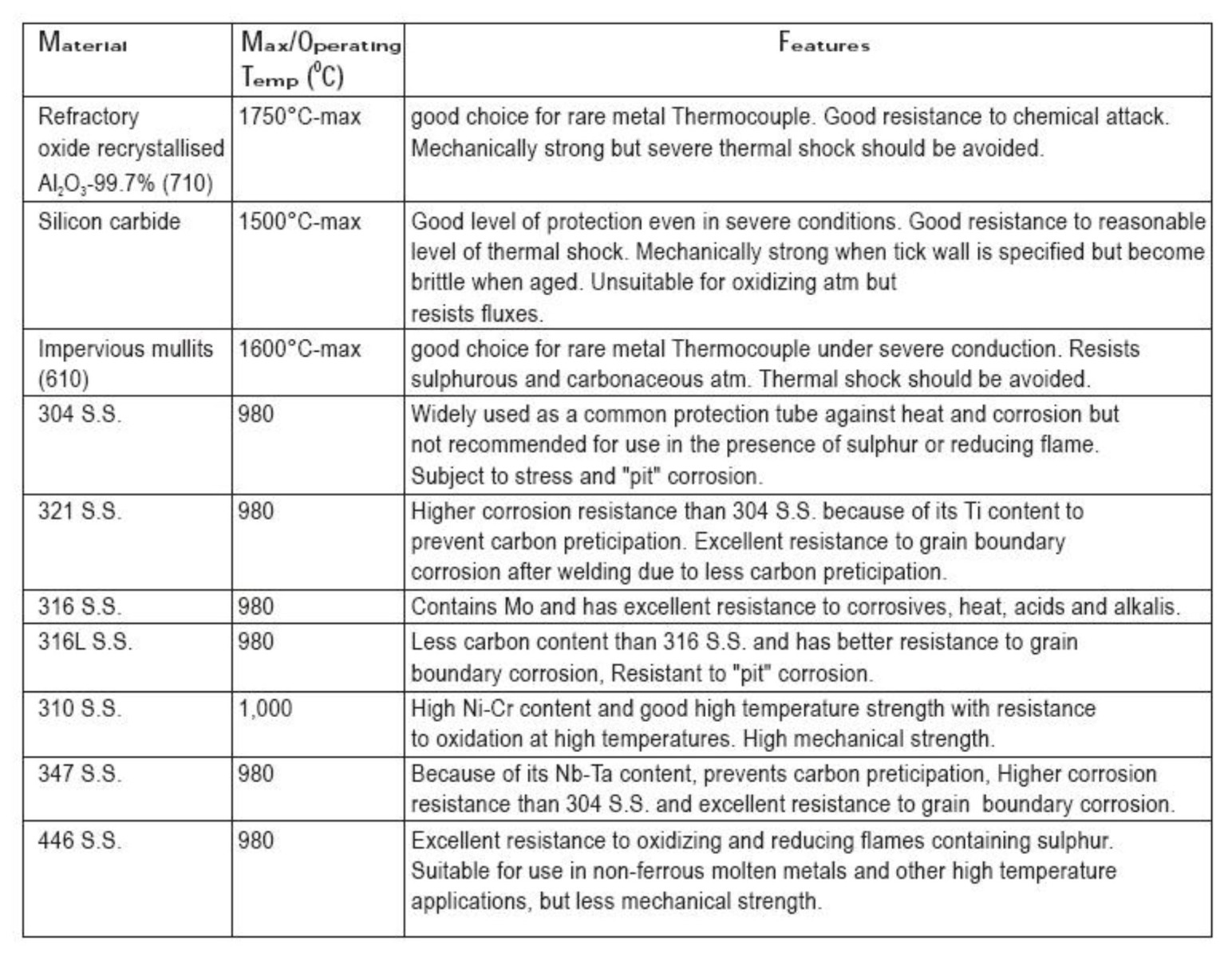
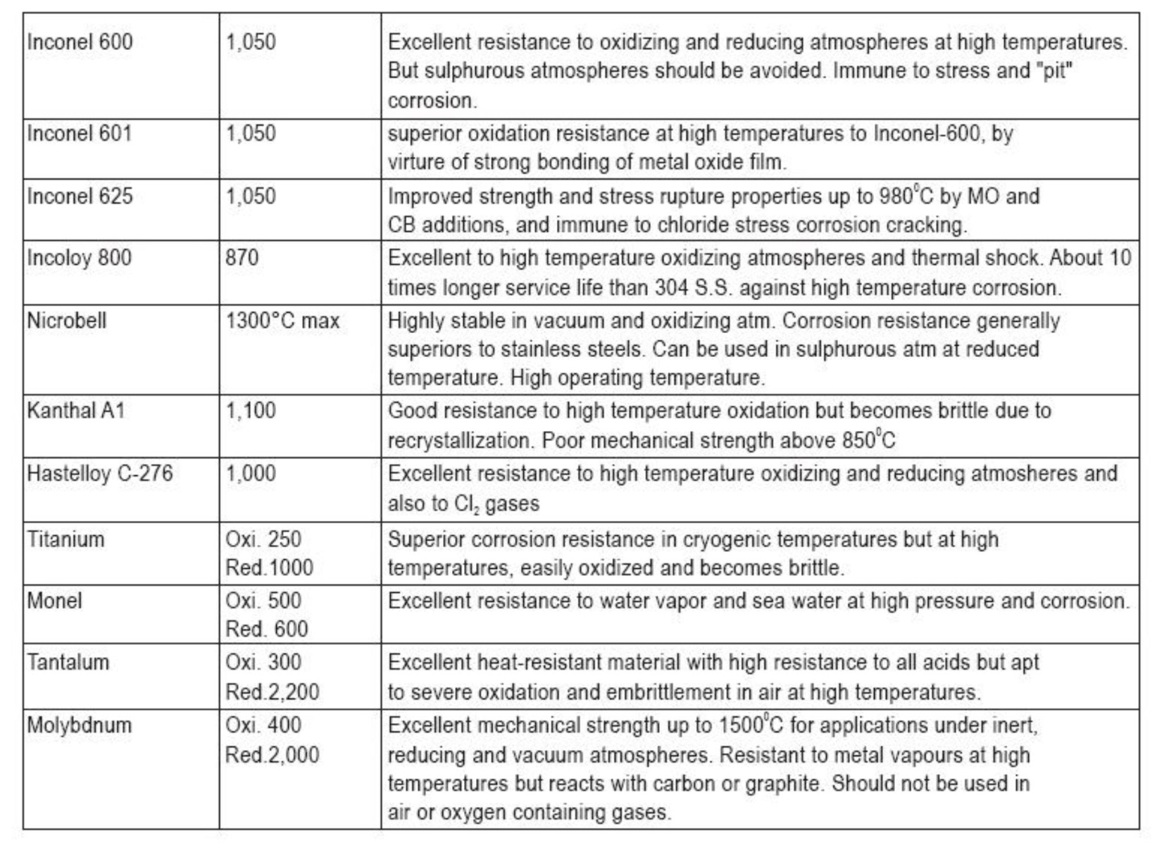
Sheath Material
Sheath material range from mild and stainless steel to refractory oxides (ceramics) and a variety of exotic material including rare metals. The choice of sheath depends on operating temperature, media characteristics, durability and other consideration including the material relationship to the type of sensor.
Protection Tubes
Caution: Due to high thermal conductivity of the metal tubes, minimum insertion length should be more than twenty five times of its overall diameter to eliminate heat conduction error.
Other protection tubes are also available.
Note: Operating and maximum temperatures of the above tubes vary depending on the measuring environment
Metallic And Non-metallic Sheath Material
The choice of metallic or non-metallic sheathing depends upon the temperature and the process atmosphere. Ceramic (non- metallic) tubes are fragile but have a high chemical resistance; they can with stand with high temperature (up to 1800°C in some case). Metallic tube, most commonly stainless steel, has mechanical advantage and higher thermal conductivity; they are generally immune to thermal shock which can easily result in the sheathing of ceramic tubes. Depending on the alloy specified, metallic sheath can be used at temperature up to 1150°C. Ceramics are superior when high purity is required to avoid sensor or product being contaminated at elevated temperature.
Ceramic Sheath With Thermocouple Element
Despite of comparatively poor mechanical properties, ceramic tubes are used; excluding the conditions where metal is to be us ed because of chemical reason or because of excessive temperature or because of any other reason. Their main application ranges between 1000 to 1800 °C. They may be in direct contact with the medium or may be used as a gas-tight inner sheath to separate the thermocouple from the actual metal protection tube. They should be mounted in hanging position above 1200°C to prevent distortion or fracture due to bending stresses. Even hairline cracks can lead to contamination of the thermocouple resulting in drift or failure. The resistance of the ceramic to temperature shock increases with its terminal conductivity and its tensile strength is greater for smaller thermal expansion coefficient. The wall thickness of the material is also important; thin walled tube is preferable to larger wall thickness. Cracks frequently developed if they are given excessively rapid temperature changes when they are quickly removed from hot furnace.
The use of an inner and outer sheath of gas-tight ceramic is therefore advisable. The outer thin walled tube protects the inner one against temperature shock though the air between them. This lengthens the life of the assembly but result in slower response.In the case of rare metal thermocouple, the ceramic has to be of very high purity. Platinum thermocouples are very sensitive to contamination by foreign atoms.
Thermowell
Thermowells provide protection to temperature probes against unfavorable operating condition such as corrosive media, physical impact and higher-pressure gas or liquid. Their use also permits quick and easy probe interchanging without the need to "open- up" the process.
Thermowell take many different forms and utilizes a variety of material (usually stainless steel); there is a wide variety of thread or flange fitting depending on the requirement of the installation. They can either be drilled from solid material for the highest pressure integrity or they can take the form of a thermo pocket fabricated from tubing and hexagonal bushes or flanges; the later construction allows longer immersion length.
Thermowells transfer heat to the installed sensor and due to that thermal inertia is introduced.
Any temperature change in the process took longer time to affect the sensor if thermowells are present; thus the response time is increased. This factor must be considered when specifying a thermowell; except when thermal equilibrium exists, a temperature measurement will probably be inaccurate to some extent.
Optimum bore is an important parameter since physical contact between the inner wall of the thermowell and the probe is essential for thermal coupling. In the case of a thermocouple, which is tip sensing, it is important to ensure that the probe is fully sheathed (in contact with the tip of the thermowell). For Pt 100 sensor, which is stem sensing, the difference between the probe outside diameter and bore must be kept to an absolute minimum.
Selection Of Thermowell
-
Materials The Longevity Factor
In general, the selection of thermowells material is governed mainly according to the corrosion the well faces. The high polish given to all stainless and Monel wells provide maximum corrosion resistance.
Well are also available in special grades of stainless steel, Chrome-molybdenum steel, silicon bronze, hastelloy B&C, nickel, titanium, and monel.
-
Connection-the Installation Factor
All threaded well are made by easily welded or brazed materials. Welding and brazing is important for the installation requiring seal. The pipe thread provides mechanical strength, and the weld or braze provides the seal.
Flanged wells (other then van stone type) consist of a bar stocks well which is solidly welded to a top quality flange. Standard construction uses a primary "J" groove weld and a bevel groove clean fillet. This double welded construction eliminates the possibility of crevice corrosion since no open joint are exposed from either inside or outside the installation.
Socket weld well are simple to install, simply weld them into place. These wells fit A.S.A. standard socket weld coupling or flanges.
-
Insertion Length-the Accuracy Factor
The distance from the tip of the well to the underside of the thread or other connection is defined as the insertion length (designated as "U"). For best accuracy this length should be greater enough to permit the entire temperaturesensitive part of element to project into the medium being measured. A properly installed element: in liquid, the element should be immersed up to its sensitive length plus one inch, and in air or gas, the element should be immersed up to its sensitive length plus three inches.
-
Bore Size-the Interchangeability Factor
Almost all installation uses several type of temperature measuring sensor. The selection of a standard bore diameter can produce extreme flexibility within the plant. The same well can accommodate thermocouple, resistance thermometer, and bimetal thermometer.
-
Tapered Or Straight Well The Velocity Rating Factor
Tapered shank provides greater stiffness with same sensitivity. The higher strength to weight ratio give these wells higher natural frequency than the equivalent length straight shank well thus permitting operation at higher fluid velocity.
-
Velocity Rating of Well
Fluid flowing by the well forms a turbulent wake, which has a definite frequency, based on the diameter of the fluid. It is important that the well have sufficient so that the wake frequency will never equal the natural frequency of the well itself. If the natural frequency of the well coincides with the wake frequency, the well would vibrate to destruction and break off in the piping.
Vibration Calculation For Bar Stock
According to ASME PTC 19.3 standard F /F < 0.8 w n Here, F = 2.64 (v/b) w 2 F = (K /L ) vE/R n f Where, F = well frequency w F = natural frequency, n v = fluid velocity in fps, b = diameter of tip of Thermo well, K = constant obtained from table 1.4 of ASME PTC 19.3, f L = length of the Thermo well, 6 E = modulus of elasticity of Thermo well material; 28x10 psi, 3 R = specific weight of metal; 0.29 lbs/inch ME PTC 19.3 standard.
Process Connection
-
Threaded Connection
Parallel or tapered thread is made for convenient installation into a weld in fitting directly into the process. Such a connection is suitable for smaller diameter well, which are not likely to be changed frequently.
-
Flanged Connection
Flanged connection is preferable if there is a need for more frequent well replacement such as high corrosion rates. The flange bolts to mating flange mounted on the process. Such a technique is more appropriate for large pipe diameter and for high- pressure application.
-
Welded Connection
Welded connection can be used when the process is not corrosive and routine removal is not required. High integrity is achieved and this technique is suitable for high temperature & pressure application.
Fitting
Installing temperature sensor assembles into thermowell or directly into the process requires the use of some kind of brass or stainless steel fitting. Fitting include various threaded unions, bayonet cap (and adapters) and flange. Adjustable compression fitting are used directly on probe to achieve the required insertion length in the process and to ensure the proper sheathing of probes into thermowell.
Adjustable flange can similarly be used to sensor assembly into the process. Bayonet caps provide a method of quick fitting into suitable adapters located in the process; this technique is widely used in plastics machinery.
Bushes and hexagon plugs are used when adjustment or removal is a lesser consideration.
The choice of fitting may be dictated by the need for pressure integrity or by physical size constraints. Compression fitting and threaded bushes can be supplied with tapered threads to achieve a pressure-tight connection.