

- Home
- About
- Products
- Contact Temperature Sensors
- Cables & Wires
- Mineral Insulated Cables
- Nickel & Thermocouple Alloy
- Industrial Heaters
- Heating Cables and Mats
- Non Contact Temperature Sensors
- Industrial and R&D Furnaces
- Temperature Calibrators
-
Circulating Chiller
- Services
-
Special Products
- Thermal Profiling System
- Industries
- Resources
- Contact Us
- Shop
Search
Resistance Theromometry
Principles And Applications Of Resistance Thermometers And Thermistor
Resistance thermometers and Thermistor are temperature sensors, which changes there electrical resistance with temperature. The superior sensitivity and stability of these devices, in comparison to thermocouples, give them important advantages in low and intermediate temperature ranges. In addition, resistive devices often simplify control and readout electronics.
Resistance thermometers are specified primarily for accuracy and stability from cryogenic levels to the melting points of metals. They are accurate over a wide temperature range and may be used to sense temperatures over a large area, and are highly standardized. The standard platinum resistance thermometer is specified by the ITS-90 (International Temperature Scale of 1990) to interpolate between fixed points in the range 13.80K (-259.35°C) to 1234.93K (961.78°C).
Resistance Thermometers
Resistance thermometers may be called as RTDs (resistance temperature detector), PRT's (platinum resistance thermometers), or SPRT's (standard platinum resistance thermometers). These thermometers operate on the principle that, electrical resistance changes in pure metal elements, relative to temperature.
The traditional sensing element of a resistance thermometer consists of a coil of small diameter wire wound to a precise resistance value. The most common material is platinum, although nickel, copper, and nickel-iron alloys compete with platinum in many applications.
A relatively recent alternative to the wire-wound RTD substitutes a thin film of platinum or nickel-iron, which is deposited on a ceramic substrate and lasertrimmed to the desired resistance. Thin film elements attain high resistances with less metal, thereby lowering cost.
Resistance/temperature Characteristics
Resistance thermometers exhibit the most linear signal with respect to temperature of any sensing device. Small deviations from straight-line response, however, dictate the use of interpolating polynomials to calculate resistance values between fixed temperature points.
The resistance/temperature characteristic for standard platinum resistance thermometers, as defined by the ITS-90, is a complex set of equations. Platinum generally follows the modified Callendar-Van Dusen equation over the range -200 to 850°C (-328 to 1562°F):
Temperature Coefficient Of Resistance
Temperature Coefficient of Resistance (TCR) has many definitions. For resistance thermometers, TCR is normally defined as the average resistance change per °C over the range 0 to 100°C, divided by R °C: 0 In one sense, TCR expresses the sensitivity of the resistive wire used in the element, as it defines the average temperature change of a hypothetical 1 thermometer.
But specifies normally use TCR to distinguish between different resistance/temperature curves of the same element material, such as the three curves platinum. Because all of these curves see widespread use, platinum TCR's must be properly specified to maintain compatibility between thermometers and instruments.
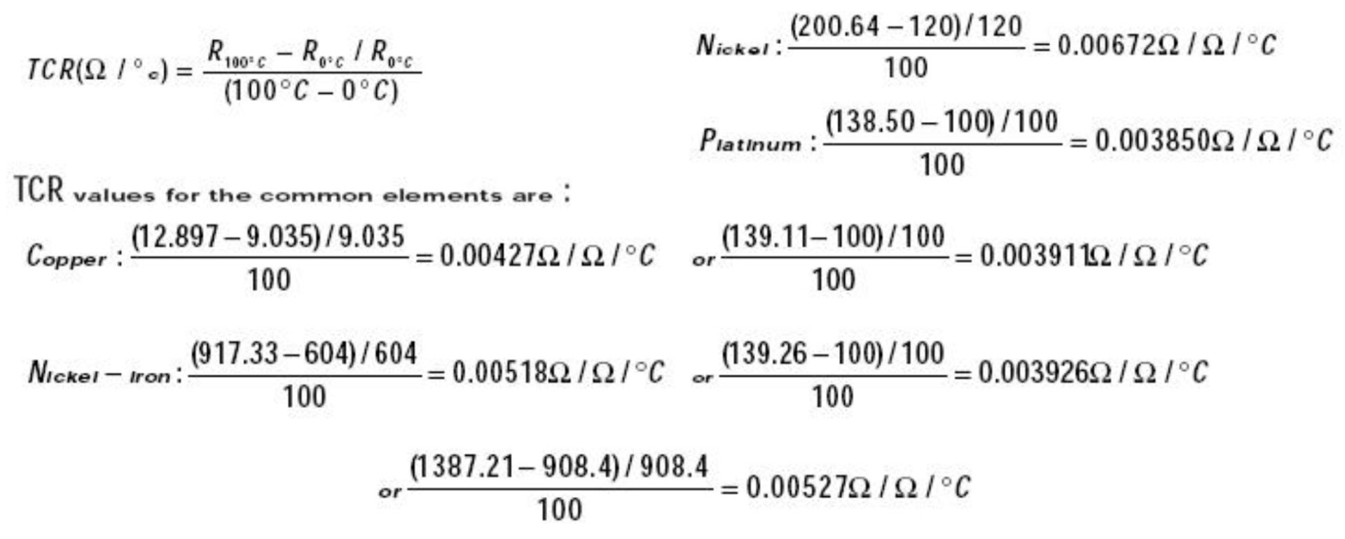 There are four primary curves specified for platinum:
- 0.003926 /°C:
Standard platinum resistance thermometers are the only PRT's that can achieve this TCR. They must have high purity platinum wire (99.999% or better) wound in a strain-free configuration. The stresses introduced in manufacturing, lower the TCR of ordinary industrial models. Several manufacturers offer industrial platinum thermometers with nominal TCR of 0.00392; TCR's around 0.003923 are achieved regularly.
- 0.003911 /°C:
This TCR is sometimes called the "U.S. Industrial Standard." It is lower than laboratory standards as the typical construction of high temperature ceramic elements impose strain on platinum wire.
- 0.00385 /°C:
DIN 43760, IEC 751, and other national and international specifications mandate this TCR.
- 0.00375 /°C:
Elements with 0.00375 TCR, intended for low-cost applications
There are few inherent advantages in specifying any particular TCR over another. Laboratory systems traditionally use reference standards with the highest-grade platinum, but industrial specify may aim instead for the greatest degree of standardization. In this case, 0.00385 TCR will be compatible with the greatest number of manufacturers.
Comparison Of Element Types
Platinum, with its wide temperature range and stability, has become the preferred element material for resistance thermometers. Furthermore, advances in element construction have narrowed the price difference between platinum and base metal thermometers. Nevertheless, nickel, copper, and nickel-iron do have benefits for many applications and should be considered. The primary advantages of the four element types are compared in Table.
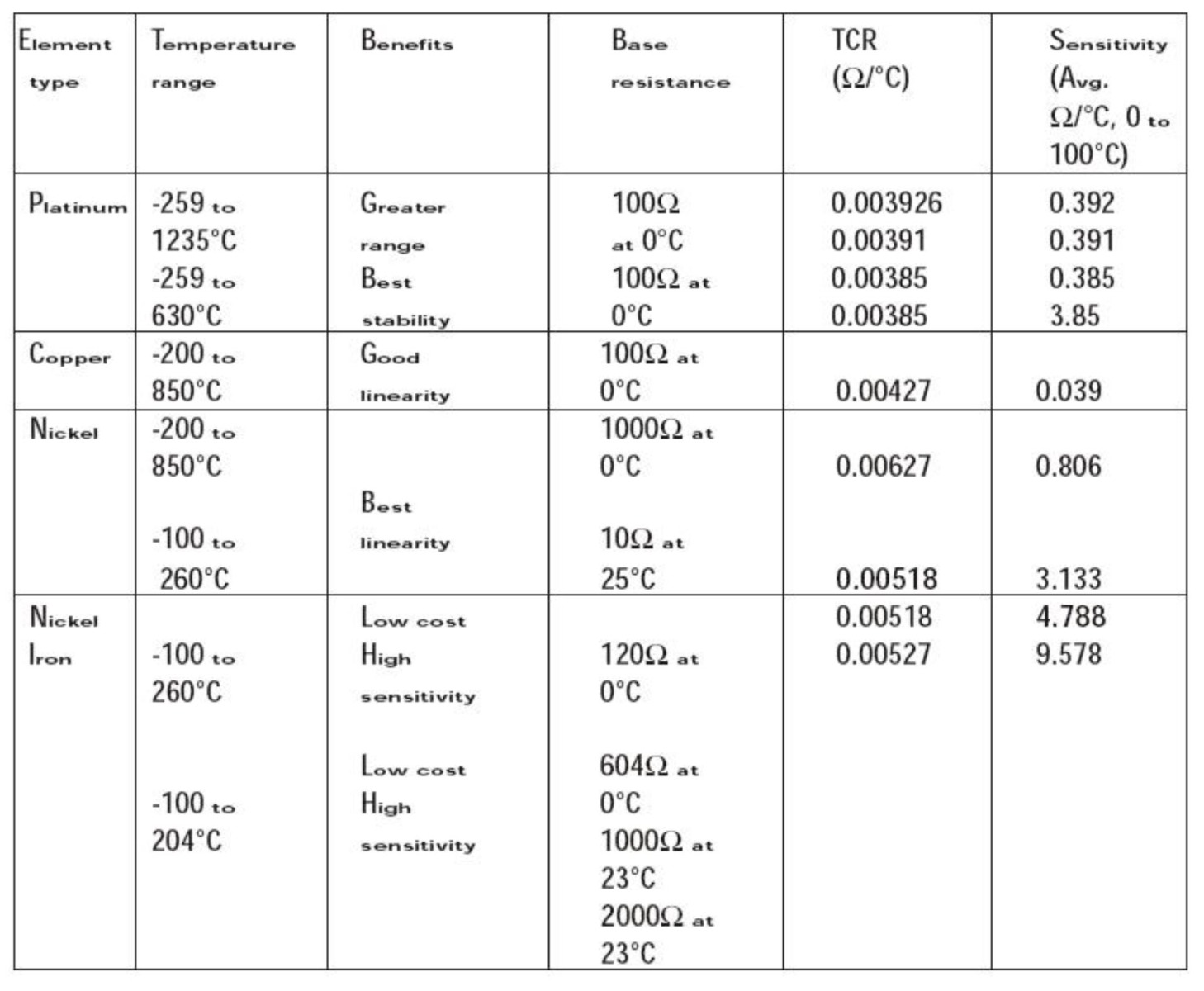 Table : Comparison of resistance thermometer element type
Effects Of Lead Wire Resistance
Because an RTD is a resistance type sensor, any resistance in the extension wires between RTD and the control instrument will add to the readings. In some cases, one can compensate for this extra resistance with adjustments at the instrument. However, this only compensates when the leads are at a constant temperature since variations in ambient temperature alter copper lead wire resistance.
Below mentioned Table shows resistance values of common copper lead wire according to sizes.
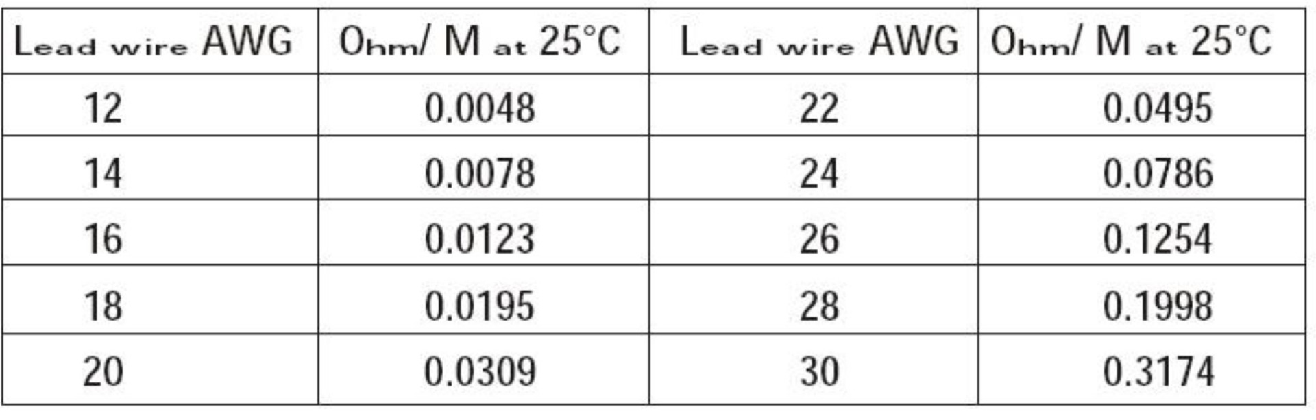
Lead wire error can be significant, especially with small diameter leads or with low sensitivity elements. In a 2-lead bridge, the lead wire resistance adds directly to readings. If leads are short enough or if sensitivity is high enough, the offset may be acceptable. When long extension runs are required between the sensor and instrument, or sensitivity is low, the specified should consider a 3-lead system. All resistance thermometers with copper elements must have three leads to offset their low sensitivity.
3-lead systems represent a practical compromise between accuracy over distance and the cost of extra leads. Although it is well suited to most industrial areas, electrical noise and contact resistance at the junction points may affect them. 4-lead circuits provide the same resistance compensation as 3-lead systems, but also relieve problems with unmatched leads, contact resistances, and thermal EMF's.
The one disadvantage of using 4-wire ohms is that we need one more extension wire than the 3-wire bridge.
This is a small price to pay if we are at all concerned with the accuracy of the temperature measurement.
Potential Sources Of Error With Resistance Thermometers
Resistance thermometer systems are susceptible to three types of errors: The inherent tolerances built into the thermometers, gradients between the thermometer and the medium to be sensed, and errors introduced along the path between the sensor and readout or control instrument. Some sources of error are electrical; others result from the mechanical construction of the thermometer.
- Interchangeability/conformity:
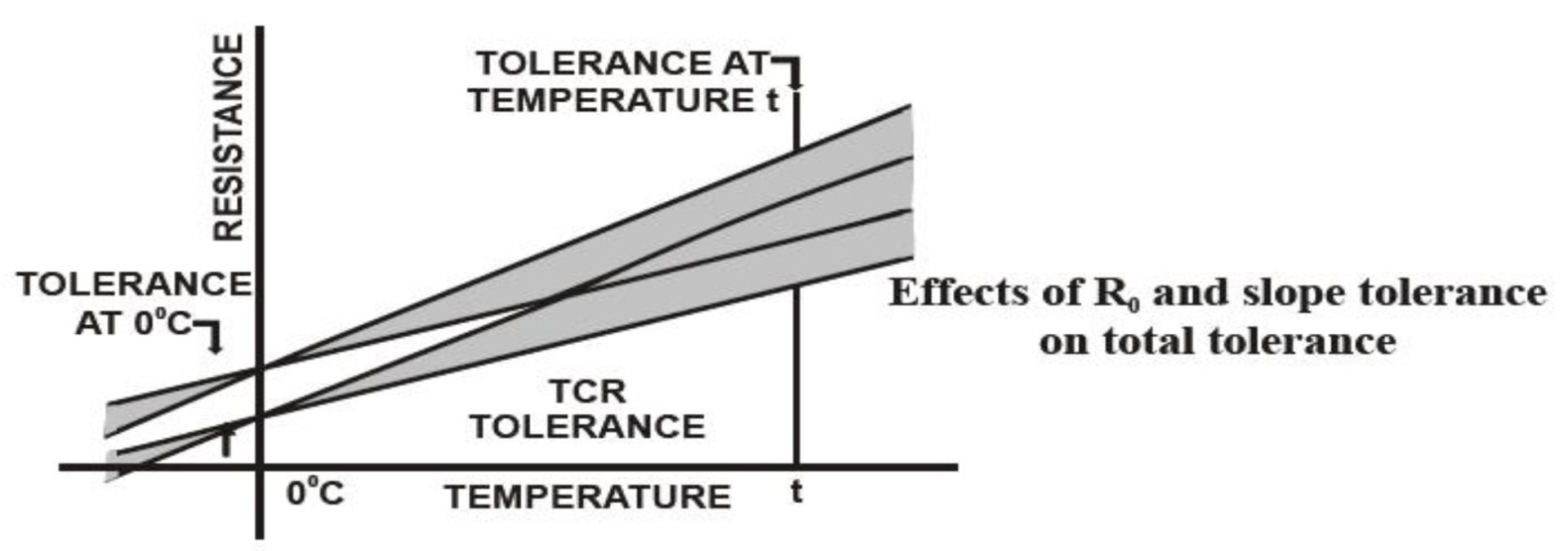
Conformity specifies the amount of resistance a thermometer is allowed to deviate from a standard curve (such as the curve produced by the Callendar-Van Dusen equation). A tolerance at the reference temperature, usually 0°C, and a tolerance on the slope or TCR. Figure 5 shows that a resistance thermometer conforms most closely to its curve at the reference temperature, while the resistance fans out above and below this reference.
For example, IEC 751, Class B, requires calibration within 0.12 (0.3°C) at 0°C, but allows TCR to deviate from nominal 0.00385 by ±0.000012 /°C. Thus, tolerance spreads to 0.8°C at 100°C, 1.3°C at 200°C, and on up to 3.8°C at 700°C. Interchangeability between two thermometers is no more than twice the value of there Conformity. Commercial platinum resistance thermometer elements are available with extremely tight tolerances, to within 0.01 (0.026°C) in some cases. When interchangeability is an overriding consideration, the specified may consider other means to achieve it. For example, manufacturers may alter their calibration procedures to fix the reference temperature and tightest tolerance at a point other than 0°C. Or if the difference between two thermometers is more important than absolute temperature, matched pairs measured to agree within a certain tolerance may is less expensive than calibrating each thermometer within a small range of nominal.
It is important to note that conformity/interchangeability specifications only denote the relative accuracy of two otherwise identical thermometers mounted side by side in the same environment. They do not include errors acting equally upon both thermometers.
- Sensitivity:
The resistance change per degree change in temperature is a function of base resistance and TCR (Temperature Coefficient of Resistance). Although a thermometer with higher sensitivity is not necessarily more accurate, a larger signal simplifies output electronics and is less susceptible to lead wire effects and electrical noise. In addition, a larger resistance produces the same voltage output with less measuring current, which helps to limit selfheating of the thermometer element.
- Insulation Resistance:
If the sensing element and leads are not completely insulated from the case, a shunting effect occurs in which the case becomes a parallel resistor and lowers apparent readings. In most industrial thermometers, with specified insulation Resistances in the 100-megohm ranges, error approaches zero. The manufacturer must take care to seal water-absorbing materials. The shunting effect decreases with low-resistance elements, which accounts for the use of 25.5 PRT's in laboratory measurements.
- Self-heating:
A resistance thermometer is a passive resistance sensor; it requires a measuring current to produce a useful signal. Because this measuring current heats the element wire above the true ambient temperature, errors will result unless the extra heat is dissipated.
Self-heating is most often expressed in mW/°C, which is the power in mill watts 2 (1000 I R) required to raise the thermometers internal temperature by 1°C. The higher the mW/°C figure, the lower the self-heating. As an example, assume a 5 mA measuring current is driven through a 100 platinum RTD at 100°C. Selfheating is specified as 50 mW/°C in water moving at 3 ft/sec. The amount of heat generated is:
2 1000 mW x (0.005 A) x (138.5 ) = 3.5 mW
The self-heating error is:
(3.5 mW) / (50 mW/°C) = 0.07°C
The generated heat increases with higher sensor element resistance (when a constant current measurement device is used), or with increasing measuring current.
The resulting error is inversely proportional to the ability of the thermometer to shed extra heat; which, in turn, depends on thermometer materials, construction, and environment.
The worst self-heating occurs when a high resistance is packed into a small body. Thin film elements, with little surface area to dissipate heat, are an example. Self-heating also depends on the medium in which the thermometer is immersed. Error in still air may be over 100 times greater than in moving water.
- Time Constant:
A time constant indicates the responsiveness of a resistance thermometer to temperature change. A common expression is the time it takes a thermometer to reflect 63.2% of a step temperature change in moving water. Response speed depends on the mass of the thermometer and the rate at which heat transfers from the outer surface to the sensing element. A rapid time constant reduces errors in a system subject to rapid temperature changes.
- Repeatability:
The degree of accord between two successive readings with a thermometer is its repeatability. Loss of repeatability results from permanent or temporary changes to the resistance characteristics of the element and may be caused by exposing the thermometer to temperatures at or beyond the endpoints of its specified range. A repeatability test cycles the thermometer between low and high temperatures; any changes to R are noted. A typical repeatability rating for an 0°C industrial platinum resistance thermometers is ±0.1°C.
- Stability:
Stability is long-term drift in thermometer readings. A typical specification would limit drift to 0.1°C per year for rated operation. Normal services at points well within the temperature rating typically cause much less drift. Drift is a consequence of the element material, with platinum being the most stable; encapsulating materials, which could contaminate the element; and mechanical stress placed on the element by expansion of winding bobbins or other supporting structures.
- Shock And Vibration:
Mechanical shock and vibration can alter thermometer readings or cause complete failure. In fact, stability and ruggedness are somewhat exclusive. A laboratory thermometer designed for maximum stability contains an unsupported element, which is far too fragile for industrial use. The elements of most industrial resistance thermometers are fully supported by a bobbin or packing material, and therefore stand up quite well to extreme environments. More likely to suffer are lead wire transition points, which should be properly immobilized. A typical RTD will meet a specification allowing shock of 100 G's of 8 milliseconds duration and vibration of 10 to 2000 Hz at 20 G's
- Packaging And Thermal Transfer:
Sheaths and other structures surrounding resistive elements should maximize heat transfer from the sensed medium, minimize heat transfer from ambient which can alter readings, and provide necessary protection of the elements. Proper materials and construction can dramatically improve reading accuracy. One strategy practicable only with wire-wound resistance thermometers versus thermistors, thermocouples, and solid-state devices is temperature averaging. An element may be wound to average temperature over lengths of up to 100 feet
Resistance Thermometer Types
Examples of commonly available resistance thermometer types, with an emphasis on the design features which take advantage of the benefits listed above, and which avoid the sources of error, are presented in the following paragraphs.
-
Standard Platinum Resistance Thermometers for Laboratory Use
NIST specifies the standard platinum resistance thermometer (SPRT) as the standard interpolating instrument used to define temperatures from -259.35 to 961.78°C. According to the ITS-90, a standard platinum Resistance thermometer must meet one of the following criteria:
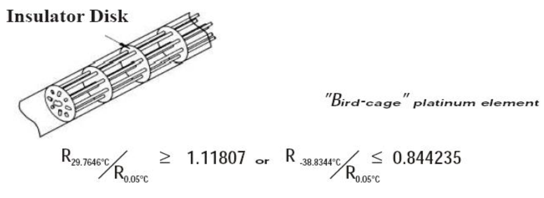
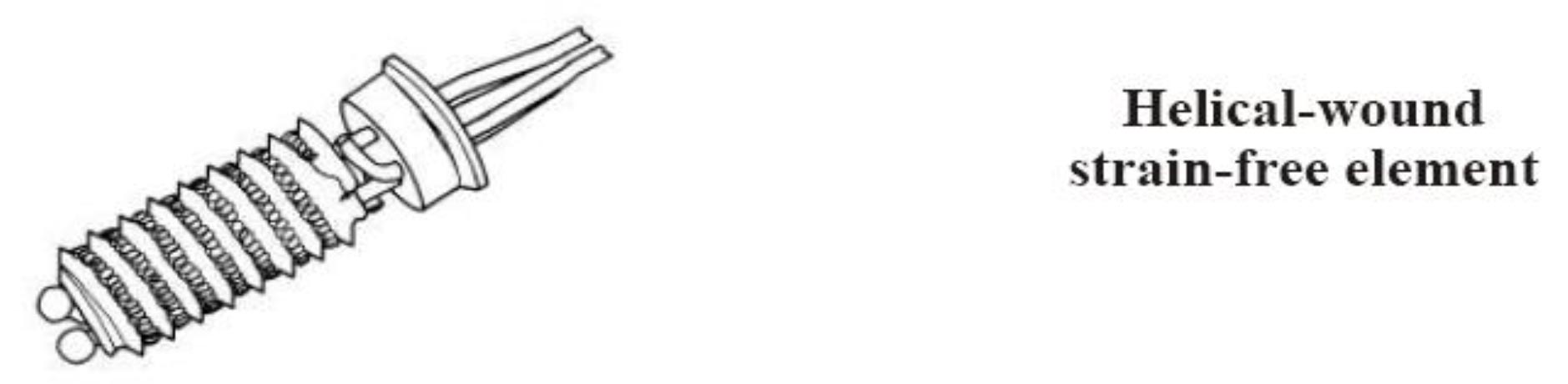
Figure shows a classic "bird cage" strain-free element, in which insulating disks supports the element wire. Figure shows a less expensive helical wind. The highest accuracy primary standards encapsulate the element within a glass or quartz sheath, although stainless steel or Inconel may be substituted for secondary, or transfer, standards. The element area must be hermetically sealed to exclude oxidizing agents and helium filled if used at cryogenic ranges.
The unsupported coils of a strain-free element are quite susceptible to damage from shock and vibration. Even a slight tap on a table can invalidate an expensive calibration.
-
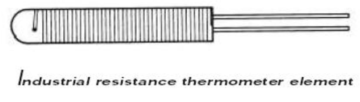
Industrial Resistance Thermometer Elements
Resistance thermometers could not have migrated from the laboratory to the industrial plant without the invention of rugged, lowcost elements. The need to encapsulate the resistive element for protection from shock and corrosive environments, without unduly straining the element, have led to a variety of technologies for constructing elements. Figure diagrams a common ceramic element. The element wire, commonly platinum, is wound around a ceramic bobbin, welded to lead wires, and coated with glass. The manufacturer must carefully match materials to prevent thermal expansion strains on the wire.
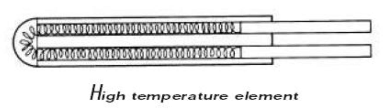
Higher temperatures are possible with the element construction of Figure. Here, a coil of platinum wire is passed through bores in a ceramic tube. The bores are then filled with a ceramic or alumina powder to cushion the coils.
Copper, nickel, and nickel-iron may replace platinum as element materials for lower temperatures, generally below 260°C. Moderate temperatures also allow the use of organic materials in element construction, enabling a wide variety of styles. Resulting benefits include lower cost and faster time response.
Thin-film elements have arrived within the last ten years and are now comparable to wire-wound ceramic elements in performance, but lower in price.
They consist of a flat substrate with a thin film of deposited platinum, lasertrimmed to proper resistance. Thin films can have high resistances, commonly 1000 ohms, without the expense of extra platinum wire. Naked elements exhibit very fast time responses, although they will respond more slowly in probes because of difficulties transferring heat to the flat element. Also, the user should be careful to limit measuring current as the small size and high resistance of thin films invite self-heating. Thin-films tend to be more fragile than wire-wound elements as well.
-
Industrial Rtd Probes
The encased probe is the standard resistance thermometer configuration for industrial process control and machinery protection. Most probe cases are stainless steel or Inconel to withstand high temperatures, although other materials offer advantages at intermediate ranges.
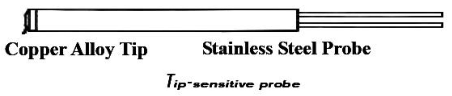
For example, the tip-sensitive probe of Figure has a copper-alloy tip which conducts heat 20 times better than stainless steel. This design improves thermal contact with sensed surfaces and reduces errors from conduction along the sheath. Standard probe diameters range from 0.125 mm to 0.250 mm. Smaller probes respond faster when directly immersed, but larger probes may fit more finely in standard thermo wells.
Probe lengths range from a few inches to ten feet or more.
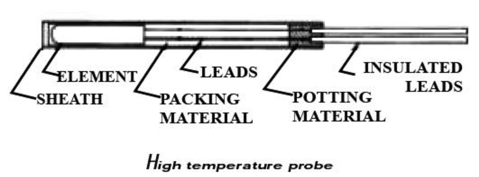
Figure shows the construction of a high temperature probe. The element fits in the tip, surrounded by high temperature powder or cement. Extension leads, normally uninsulated, extend back from the element and are encapsulated by powder, cement, or bored ceramic spacers. External leads, often insulated with PTFE or glass braid, are potted with cement at the entry point to seal against moisture.
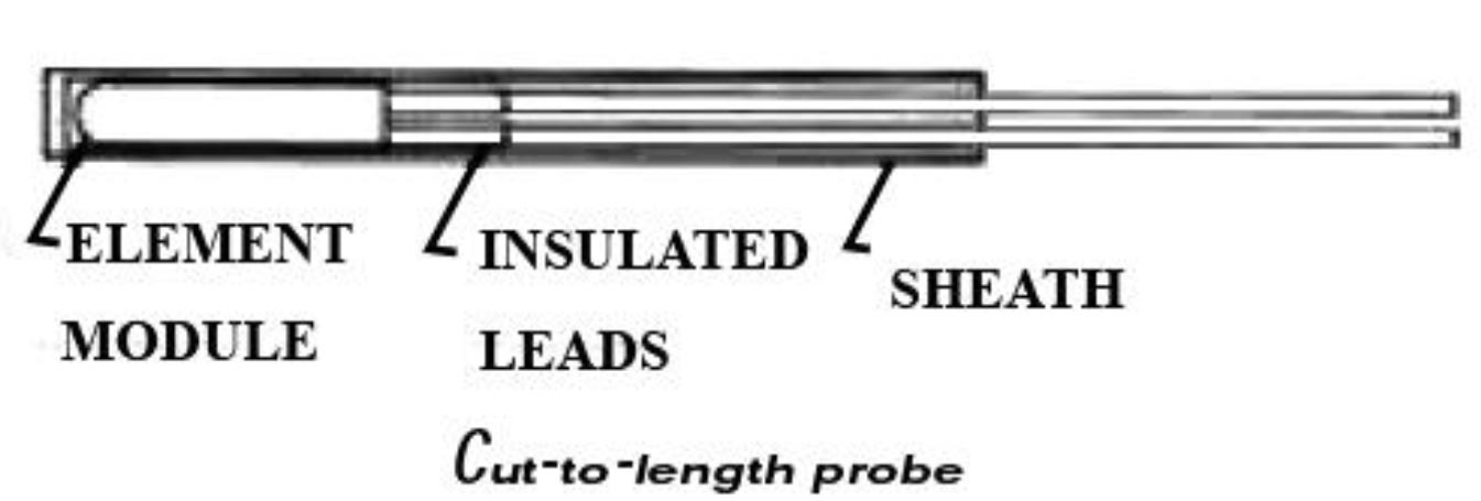
The alternative construction of Figure places the element, potting, and lead transitions within a module at the tip of the probe. This design allows the user to cut the probe to required lengths. Temperature is limited to the rating of the external lead wire insulation: 260°C (500°F) for PTFE, up to 550°C (1022°F) for insulations such as woven mica/glass.
Probe Assemblies
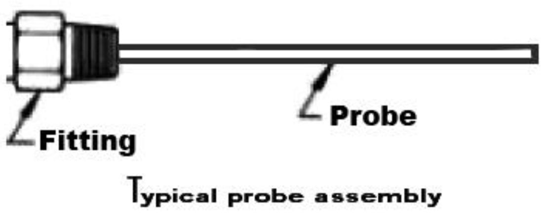
A wide variety of mounting fittings and accessories aid probe installation. Selection depends on the nature of the medium being sensed and cost requirements.
Direct immersion of a probe into a liquid requires a fitting with a pipe thread, which may be adjustable or welded on the probe. Figure shows a typical assembly, with one thread for mounting the probe and another for a connection head. Connection heads provide a transition between probe leads and external signal wires.
Mounting in a solid material is best accomplished with a spring-loaded holder, which may be fixed or adjustable.
Spring loading provides good contact of the probe tip against the bottom of the hole and dampens potentially damaging vibration
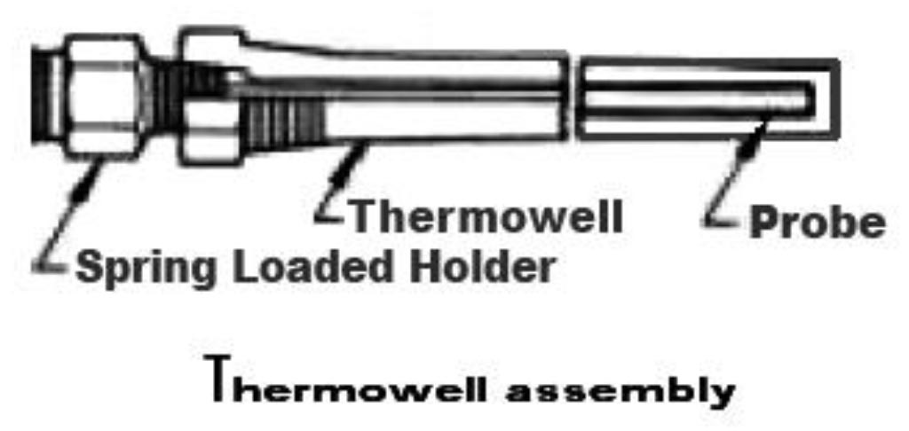
When liquids are particularly corrosive, under high pressure, or fast flowing, a thermo well may be necessary. A thermo well is a tube, closed at one end, which protects the probe and allows its removal without breaking the liquid seal. Many materials and styles are available to match application requirements. Thermo wells drilled from solid bar stock provide the highest-pressure ratings, but welded models cost much less. Figure shows a typical thermo well assembly, including a spring-loaded holder for enhanced thermal response and reliability.
Flexible Resistance Thermometers
The encased probes described above do not adapt well to sensing flat surfaces. Unlike thermocouple junctions, which can be welded directly to metal surfaces, resistance thermometers present a certain amount of bulk; and heat losses to ambient air may affect readings.
Small flat elements, such as thin films, may mount on surfaces, but fragile element and lead wire connections make installation difficult.
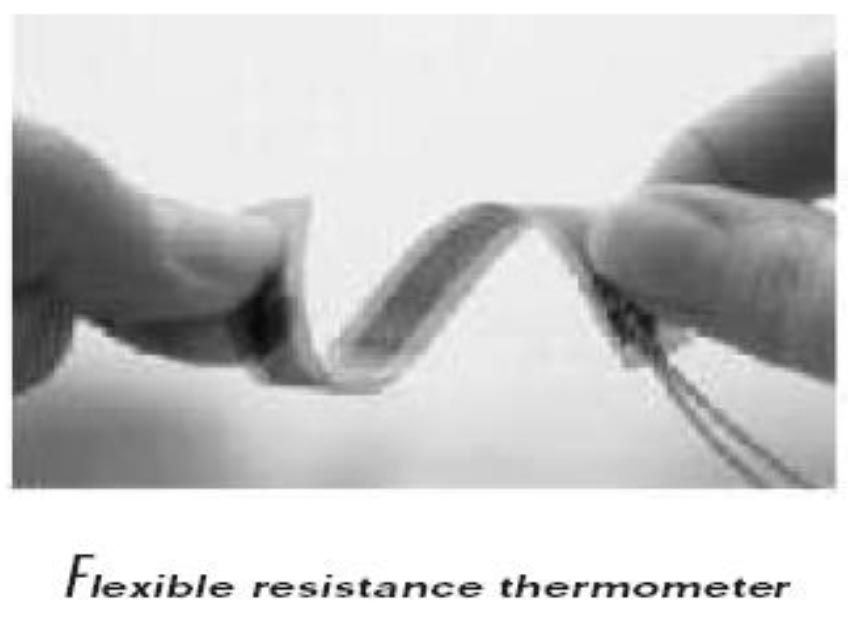
Figure shows a flexible resistance thermometer with a wire-wound sensing element sandwiched between insulating layers. It conforms closely to sensed surfaces, and has thin insulation to readily transmit heat to the sensing element. The wire element may be wound to nearly any size to average out temperature gradients, and the flexible construction can withstand extreme shock and vibration.
special Purpose Resistance Thermometers
Resistance thermometers readily adapt to most process control and thermal equipment designs. The user may specify cases with axial leads for circuit board mounting, flat packages for clamping to surfaces, miniature cases for embedment into metal blocks, and any sheaths and fittings, which can be produced by a machine shop. In addition, wire windings may be configured to sense over large areas.
Where To Use Resistance Thermometers
- Accuracy and stability are the foremost goals of the application
- Accuracy must extend over a wide temperature range
- Area, rather than point, sensing improves control
- A high degree of standardization is desirable.