

- Home
- About
- Products
- Contact Temperature Sensors
- Cables & Wires
- Mineral Insulated Cables
- Nickel & Thermocouple Alloy
- Industrial Heaters
- Heating Cables and Mats
- Non Contact Temperature Sensors
- Industrial and R&D Furnaces
- Temperature Calibrators
-
Circulating Chiller
- Services
-
Special Products
- Thermal Profiling System
- Industries
- Resources
- Contact Us
- Shop
Search
Heat Flux Sensors
Introduction
Amount of Heat Transfer from or to a surface per unit time per unit area is termed as heat flux. Heat flux is also called as heat flux density, heat flow rate and its SI unit is watt per meter square (W/m2). It has both magnitude and direction. Therefore heat flux is a vector quantity. This heat flux is measured by the temperature change bought by the the efect of heat flux sensor. There are three modes of heat transfer:-
- Conduction.
- Convection.
- Radiation.
Conduction and convection requires medium for heat transfer while on the other hand radiation does not required any medium. High-intensity radiations cannot be measured directly by fragile thermopiles and bolometers as these instruments could be burned out. A gardon guage heat flux sensors can measure the high thermal radiation intensities.
Gardon Guage Sensor
Construction and Working Principle
Heat flux sensor designed for high-intensity radiation measurements. Heat is absorbed in a thin metallic circular foil, which act as constant temperature reservior. This heat is then transferred radially (parallel to the absorbing surface) to a heat sink made of copper welded around the foil's circumference. The temperature distribution at the center foil is maximum and minimum at the circumference due to the dissipation of heat to the heat sink. A single dierential thermocouple between the foil centre and foil edge temperatures generates the voltage output.
Theoretical Analysis Of Performance
A thin circular foil of thickness and of radius R is brazed around its circumference to a large heat sink maintained at constant temperature. This foil absorbs thermal radiation of intensity q. In order to measure accurate incident radiation steady state analysis is done. In steady state condition, the heat absorbed by the foil is equal to the heat dissipated via conduction.
Under Steady state condition :-
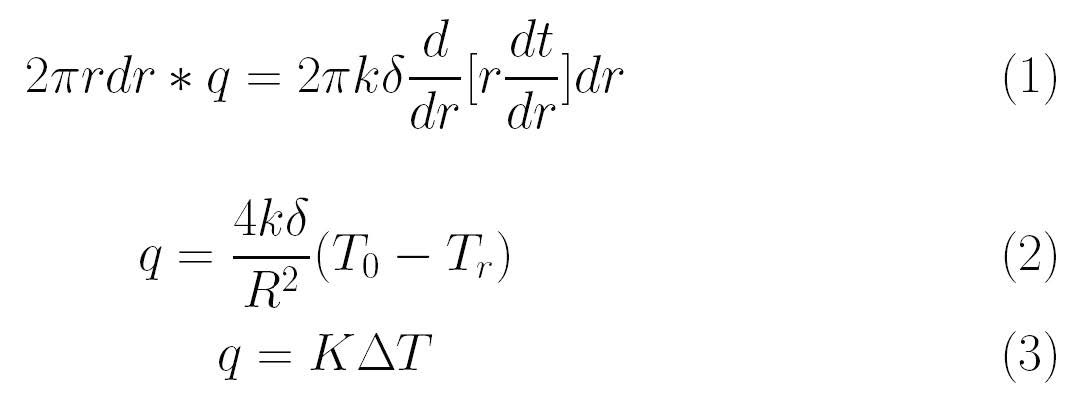
In order to find the speed of response of the sensor i.e. time constant, We need to analyse the unsteady state condition. In unsteady state condition heat incident on the foil is equal to the heat absorbed by the foil in time interval t. Under unsteady state:-
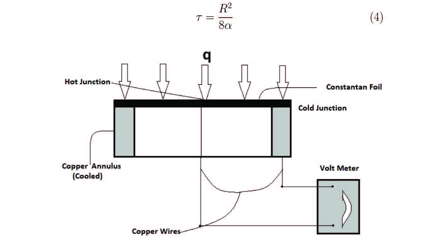
Figure 1: Schematic diagram of Gardon foil guage.
In above derivations the thermal conductivity is assumed to be constant for the constantan foil. However, in practical applications the thermal conductivity is not constant leading to non linear relationship between temperature gradient and intensity. Besides this, the temperature emf relation in constantan and copper is also non-linear. This is in favorable coincidence in this case as these two nonlinear effects cancel each other to produce a linear temperature-emf relationship in copper constantan radiometers.
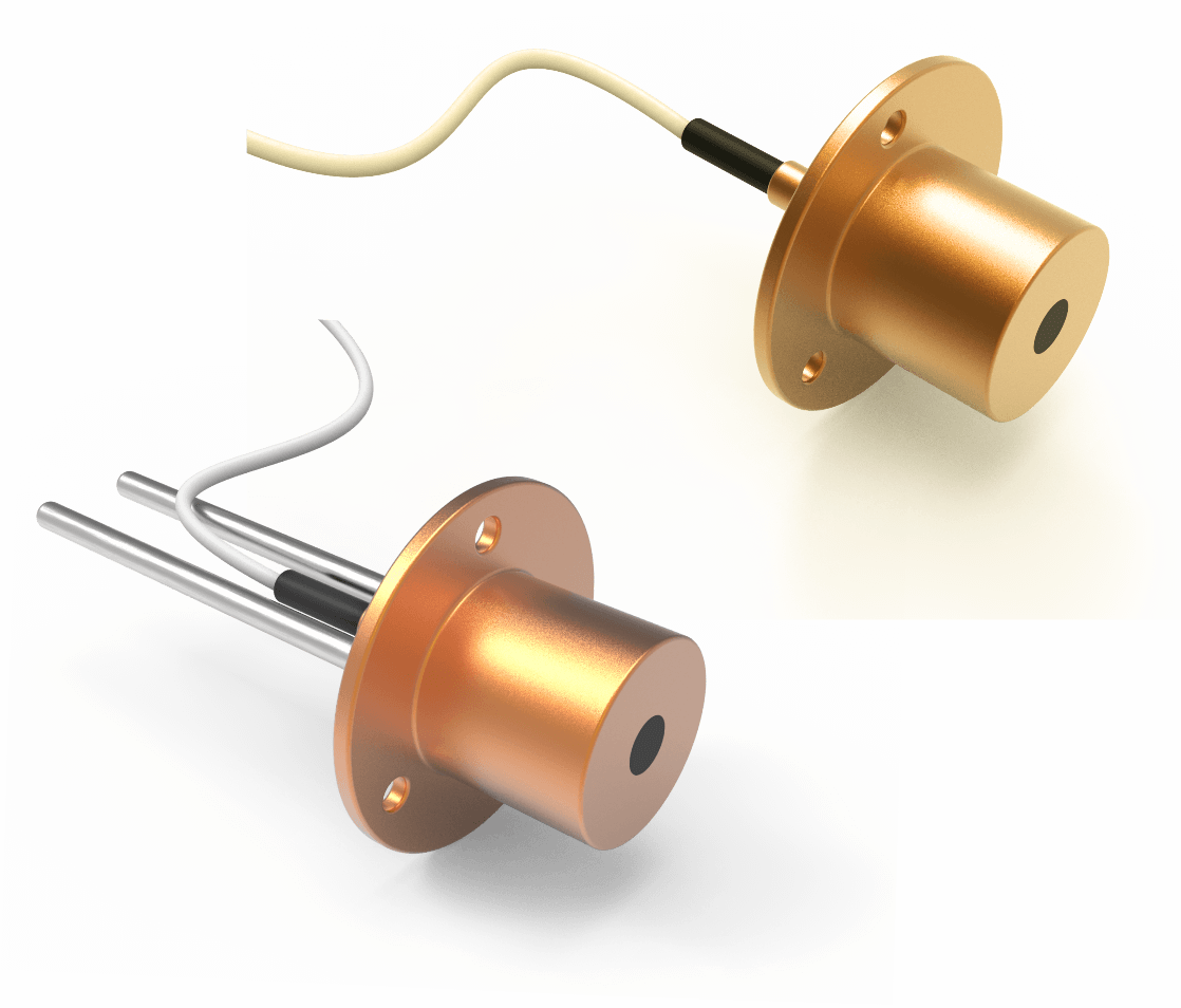
Figure 2: Heat flux sensor cooled and uncooled developed by Tempsens instrments pvt. ltd.
Sensitiveness or Responsivity is the ratio of the voltage output to the heat flux measured. For a particular radiometer, responsivity is constant.
Sensitivity = OutputV oltage / Heat flux
Design and Calibration
We have designed our heat flux sensors according to the theoretical analysis with suitable foil thickness and diameter of foil. In order to calibrate heat flux sensor. An experimental setup is prepared. The experimental apparatus is made of a heat flux sensor, a data acquisition unit, and a PC. The calibration of gauge is dependent on the radiated flux and measuring output or response of the sensor. The sensor based upon thermocouple response and output measured with precise volt- meter (measuring unit). The calibration constant of gauge at given flux is simply a flux to response ratio. In this process, we measure the heat flux from highly stable heat source radiating on the heat flux sensor. Firstly our heat source i.e. blackbody furnace, is heated which generate radiation from cavity graphite strip at very high temperature. Then, place the test and standard heat flux sensors at some equal dis-tances from the graphite strip. Then manually control the voltage of furnace by increasing or decreasing until you get 10 millivolt output in the standard heat flux sensor ensuring input radiation of 10 watt=cm2. Express the test sensor output values in milivolts, then perform the lin- ear regression analysis for the heat flux and sensor output. The slope of the linear regression gives the responsivity/sensitivity of the sensor in mV=(W=cm2) and at last plot the calibration datam to chek the accuracy of the test guage. We use black body furnace as heat source. The designed heat flux sensor is then placed against the furnace and the voltage is measured.
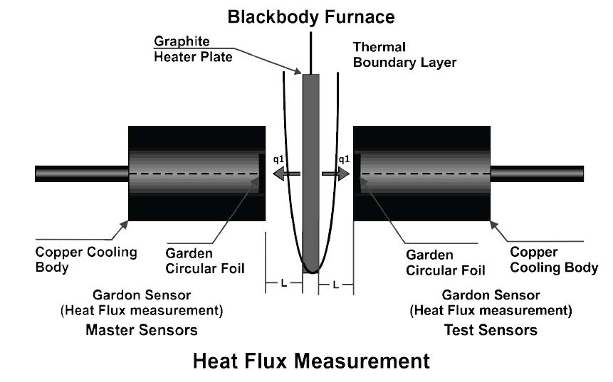
Figure 3: Schematic representation of experimental setup.
These voltage values are multiplied by the sensivity of the master guage. Then the obtained heat flux of the test guage is plotted with its corresponding voltage. Then data points in test guage graph are linearly fitted. The slope of the linear fitted curve gives the actual sensitivity of the test guage. The accuracy of the test guage is calculated by taking reference of the master guage.
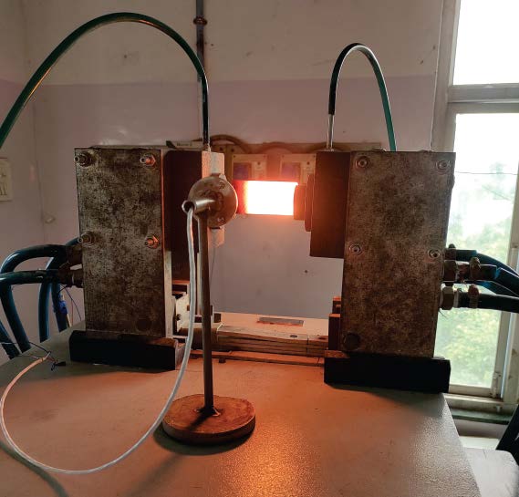
Figure 4: Heat flux sensor calibration using black body furnace at Tempsens.
A test heat flux sensors of 30 watt/cm2 is calibrated using the above explained experimental setup. The obtained responsivity of the test sensor is 0.315. Hence the accuracy is with in 5%
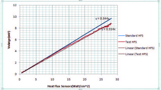
Figure 5: Calibration of heat flux sensor of with standard guage.
Features :
- Measures intensity directly.
- Measure it calorimetrically, i.e., without reference to spectral quantity.
- Less time constant.
- Mechanically robust.
- Give signals that are capable of being recorded without amplification