

- Home
- About
- Products
- Contact Temperature Sensors
- Cables & Wires
- Mineral Insulated Cables
- Nickel & Thermocouple Alloy
- Industrial Heaters
- Heating Cables and Mats
- Non Contact Temperature Sensors
- Industrial and R&D Furnaces
- Temperature Calibrators
-
Circulating Chiller
- Services
-
Special Products
- Thermal Profiling System
- Industries
- Resources
- Contact Us
- Shop
Search
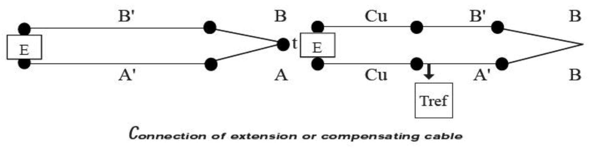
Extension Leads and Compensating Cable
It is often desirable to connect a thermocouple probe, as a part of a very long circuit from the sensor itself to a remote reference unit and/or measuring instrument. Yet, we would avoid the expense of high specification thermocouple cable on a long run.
Connecting cheaper cable would be ideal but we need to do so without having to take particular care that temperature, where the connection is made, is known and taken in to account. When connecting thermocouples to instruments, it is essential that a cable is used, which has the same emf output as the thermocouple; otherwise spurious emf is generated at these junctions. The best solution is to use the same material as the thermocouple (extension cable).The tolerances for these are listed in the following tables.
A cheaper alternative is to use compensating cables, the alloys of which are different from those of the thermocouple but have the same output over a limited temperature range.Compensating and extension grades of wire are supplied in the bright-annealed condition.
For this to be possible, the thermoelectrics properties of the additional conductor must not differ too much from those of the thermocouple itself. Extension and compensating cable provide convenient, economic solution-each with its pros and cons. Extension cable uses wire of nominally the same conductor as the thermocouple itself, which thus inherently possess similar thermo power characteristics, and with no connection problems.
Miss-match error arising from high connecting box temperature is likely to be relatively small. These cable are less costly then thermocouple wire, although not cheap, and are usually produced in a convenient form for carrying over long distance typically as flexible wiring or multi-core cables. They are recommended for best accuracy.
Compensating cables, on the other hand are less precise, but cheaper. They harness quite different relatively low cost alloy conductor materials, whose net thermocouple in question, but which not them as faithfully as do extension cable. Thus, the combination develops similar output as those of the thermocouple, but the operating temperature range has to be restricted to keep miss-match error acceptably small.
Insulation
Insulation used in cable is:
- PVC
- PTFE
- GLASS FIBER
- Silicone rubber
- Fire resistance mica cable
PVC
It is cheaper then other; it is used for the temperature range 30°C to 105°C. It is available in twisted, flat, &multi pair combination. There is arrangement of options-with ripcord, PVC sheathed, screened, with a copper wire drain, or steel wire armoured construction-the conductor itself being solid or stranded.
PTFE
It is used for high temperature range 273°C to 250°C, or 300°C for short period. It is available in twisted, flat, & multi pair combination, but not steel wire armoured versions. It withstands attack from virtually all known chemicals, oils & fluids. All over the cable is made in extruded form and is therefore gas, steam & water tight which makes them most suitable for application such as autoclaves or sterilizers.
Glass fiber
It is used for higher temperature range. It handles up to 50°C to 400°C, in some cases it is used up to 800°C. Single and multi- pair varieties are available in flat and twisted with many of the options. Ceramic fiber cable are used up to 1400°C which are suitable for use at normal air ambient temperature where there is a possibility of a hot spot, which might damage lower rated cables as PVC.
Silicon rubber
Excellent properties for the propagation of flame by in corporation of flame retardant silicon rubber compounds. Suitable for situations where there is a risk of fire. Ideal for application where, for short period of time, the temperature can fluctuate, which would cause other cable to become inflexible and brittle.
Fire resistance mica cable
Resistance to a temperature of 750°C for at least three hours in accordance with the flame test requirement. Essential for situations where it is of strategic importance to ensure that the cable continues to function during a major crisis-involving fire. The cable incorporates a high temperature rated MICA glass tape with a XLPE insulation on the cores and low smoke and fume material on the bedding and/ or outer sheath. Sheath material used is halogen free.
Color-coding &specification
Extension lead & compensating cable are distinguished by color code and letters, to ease identification of the whole circuit. Although the code used to be different from country to country, standard color has been adopted for all standard thermocouple. B S 4937 part 30(1993) provides standards of coding. In this there is no difference between extension & compensating cable- color codes. With compensating cable, the different alloy used is distinguished by KCA & KCB.
Armoured flame retardant PVC
Armoured flame retardant PVC is extremely useful where there is a need to run a number of thermocouple signals back to instrument. All cable incorporate insulated cores, bedding and overall sheath in flame retardant PVC, which has good properties for the reduced propagation of flame. The mechanical properties of these cables meet the requirement of BS EN 60811:1995.
Non-Armoured flame retardant PVC
Non Armoured flame retardant PVC is extremely useful where there is a need to run a number of thermocouple signals back to instrument. All cable incorporate insulated cores, bedding and overall sheath in flame retardant PVC, which has good properties for the reduced propagation of flame. The mechanical properties of these cables meet the requirement of BS EN 60811:1995.
Base Metal Extension Wires And Compensating Cables Types And Tolerances
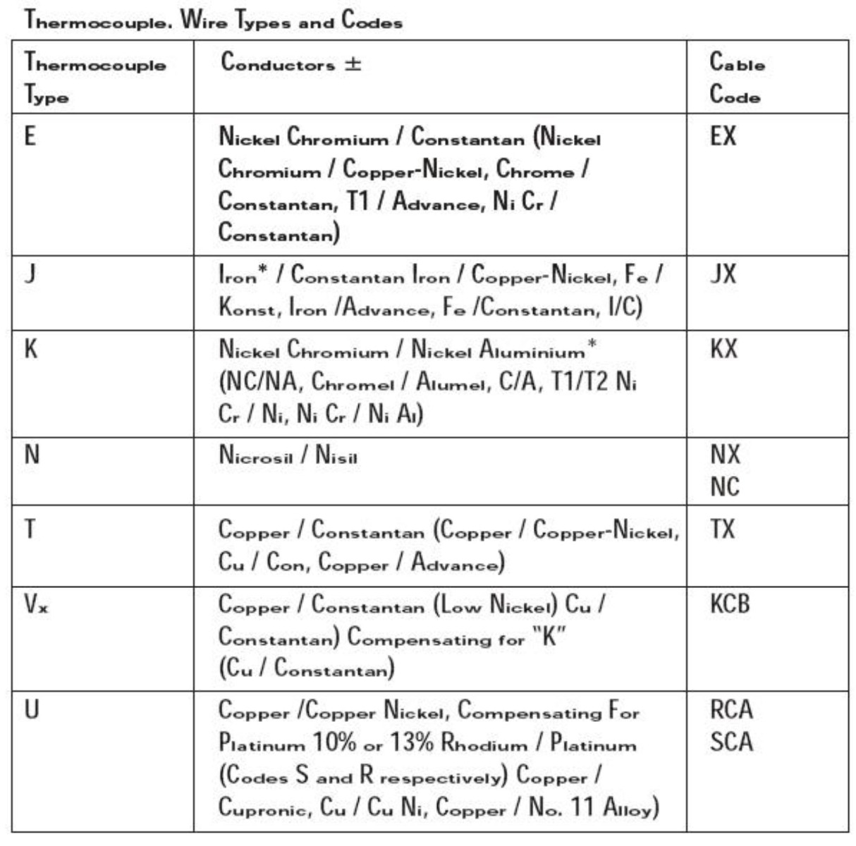
Thermocouple Wire Tolerances
The figure shown in the tables is those appropriate to the measuring junction temperature in the final column. In most cases, the error expressed in degrees Celcius will be larger at lower thermocouple junction temperatures.

Note:
- Cable temperature range may be restricted to figure lower then those shown in the table because of temperature limitation imposed by the insulant.
- A cable comprising two copper conductors may be used with type B thermocouple. The expected maximum additional deviation within the cable temperature range 0°C to 100°C is 40 µV. the equivalent in temperature is 3.5°C when the measuring junction of the thermocouple is at 1400°C.